background image

Maintenance and care


28


02.00 | KSF3, KSF3-LH, KSF3-F | Assembly and Operating Manual | en | 

1467140


7


Maintenance and care


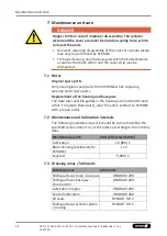
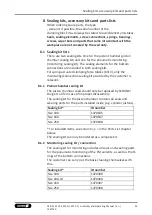
DANGER 


Danger to life in case of improper disassembly. The cylinder 

piston and the cover are under tremendous spring force, which 

can eject the parts.


Any work requiring disassembly of the cover or cylinder piston 

may only be performed by SCHUNK.


For basic cleaning, only the base jaws with their attachments, 

as well as the chuck piston and the cover strip may be 

dismantled.


7.1


Notes


Original spare parts


Only use original spare parts from SCHUNK when replacing 

wearing parts/spare parts.


Replacement of the housing and base jaws


The base jaws and the guides in the housing are matched to each 

other. To replace these parts, send the entire product to SCHUNK 

with a repair order.


7.2


Maintenance and lubrication intervals


The following maintenance work should be carried out after the 

specified cycle numbers or, at the latest, according to the monthly 

data.


Maintenance work


Interval [cycles/month]


Lubrication


10,000 / 1


Basic cleaning (exclusively by 

SCHUNK)


- / 12


Leak test


5,000 / 1


7.3


Greasing areas / lubricants


Greasing areas


Lubricants


Sliding surfaces body - base jaw


LINOMAX 200


Sliding surfaces base jaw - 

chuck piston


LINOMAX 200


Lubrication nipples


LINOMAX 200


Central lubrication


LINOMAX 200


All seals


RENOLIT HLT 2


Sliding surfaces cylinder piston


- housing


RENOLIT HLT 2


Summary of Contents for TANDEM KSF3 100

Page 1: ...Translation of Original Operating Manual TANDEM Clamping Force Block KSF3 KSF3 LH KSF3 F Assembly and Operating Manual ...

Page 2: ...n 02 00 04 01 2022 en Dear Customer thank you for trusting our products and our family owned company the leading technology supplier of robots and production machines Our team is always available to answer any questions on this product and other solutions Ask us questions and challenge us We will find a solution Best regards Your SCHUNK team Customer Management Tel 49 7572 7614 1300 Fax 49 7572 76...

Page 3: ...ent 9 2 9 Notes on safe operation 9 2 10 Transport 10 2 11 Malfunctions 10 2 12 Disposal 10 2 13 Fundamental dangers 10 2 13 1 Protection during handling and assembly 10 2 13 2 Protection during commissioning and operation 11 2 13 3 Protection against dangerous movements 11 2 13 4 Notes on particular risks 12 3 Technical data 14 4 Tightening torques for screws 18 5 Assembly and connection 19 5 1 A...

Page 4: ... 3 Adjustment of the pneumatic jaw end position monitoring PM 33 7 4 4 Leak test 33 8 Sealing kits accessory kits and parts lists 35 8 1 Sealing kit lists 35 8 1 1 Piston chamber sealing kit 35 8 1 2 Monitoring sealing kit connection 35 8 2 Accessory kits 36 8 3 Parts lists 36 9 Assembly drawings 40 9 1 KSF3 KSF3 LH 40 9 2 KSF3 F 41 10 Translation of the original declaration of incorporation 42 11...

Page 5: ...ng and may differ from the actual product design Inadditiontotheseinstructions thedocumentslisted under 1 1 2 5 are applicable 1 1 1 Presentation of Warning Labels To make risks clear the following signal words and symbols are used for safety notes DANGER Danger for persons Non observance will inevitably cause irreversible injury or death WARNING Dangers for persons Non observance can lead to irre...

Page 6: ...s intended under the following conditions Observe the applicable documents 1 1 2 5 Observe the ambient conditions and operating conditions 2 6 8 Observance of the specified care and maintenance instructions 7 28 Parts touching the workpiece and wear parts are not included in the warranty A cycle consists of a complete clamping process Open and Close 1 3 Scope of Delivery Clamping force block KSF3 ...

Page 7: ...s that are not permissible Workpieces are not properly clamped Safety regulations are disregarded and persons are working at this product for example to machine clamped workpieces without additional protective equipment The technical data specified by the manufacturer are exceeded during usage It is used with machines systems or workpieces that are not designed to be used with it 2 3 Constructiona...

Page 8: ...defined application parameters 3 14 Make sure that the product is a sufficient size for the application Ensure that maintenance and lubrication intervals are observed 7 28 Ensure that the environment is free from ferromagnetic particles or chips 2 7 Personnel qualification Inadequate qualifications of the personnel If the personnel working with the product is not sufficiently qualified the result ...

Page 9: ...d wear the required personal protective equipment Observe the valid safety and accident prevention regulations Wear protective gloves to guard against sharp edges and corners or rough surfaces Wear heat resistant protective gloves when handling hot surfaces Wear protective gloves and safety goggles when handling hazardous substances Wear close fitting protective clothing and also wear long hair in...

Page 10: ...t until the malfunction has been rectified Test the product after a malfunction to establish whether it still functions properly and no increased risks have arisen 2 12 Disposal Handling of disposal The incorrect handling of disposal may impair the product s safety and cause serious injuries as well as considerable material and environmental harm Follow local regulations on dispatching product com...

Page 11: ... zone Never step into the danger zone during operation 2 13 3 Protection against dangerous movements Unexpected movements Residual energy in the system may cause serious injuries while working with the product Switch off the energy supply ensure that no residual energy remains and secure against inadvertent reactivation Never rely solely on the response of the monitoring functions dynamic pressure...

Page 12: ...nt of pneumatic pressure failure Ensure stable compressed air supply Use pressure maintenance valves WARNING Risk of injury in the event of workpiece loss due to failure or pressure reduction of the compressed air Ensure stable compressed air supply Use pressure maintenance valves WARNING Risk of injury from falling parts during transport assembly and disassembly of the product and its accessories...

Page 13: ...AUTION Ergonomic risk to the musculoskeletal system when lifting and transporting the product using manual force Use load handling equipment for lifting and transporting CAUTION Allergic reactions or irritation due to skin or eye contact with lubricants on the product In case of foreseeable contact with lubricants on the product e g when lubricating or cleaning wear protective equipment protective...

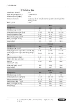
Page 14: ...peat accuracy mm 0 01 0 01 0 02 Max jaw height mm 60 60 150 Weight kg 4 3 12 5 39 4 Designation KSF3 LH 100 160 250 Stroke per jaw mm 6 8 15 Clamping force range without turbo kN 3 5 9 15 14 21 Clamping force range with turbo 6 bar kN 8 11 22 34 33 46 Opening pressure bar 6 9 6 9 6 9 Max turbo pressure bar 6 6 6 Repeat accuracy mm 0 01 0 01 0 02 Max jaw height mm 150 200 500 Weight kg 4 4 12 7 39 ...

Page 15: ...ividual forces occurring at the chuck jaws at distance H see also catalog The maximum clamping force is achieved in the open position The min clamping force is applied shortly before the closed position End position spread after 100 consecutive strokes Dependency clamping force to jaw stroke Clamping force Jaw position Opened Closed ...

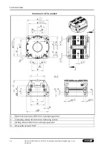
Page 16: ...bly and Operating Manual en 1467140 Technical data Dimensions of the product 1 Optional Z variant 0 01 mm to clamping center 2 Clamping sleeve 0 04 mm to clamping center 3 Fitting screw 0 02 mm to clamping center 4 Only with variant PM ...

Page 17: ... Ø C 6H7 x 12 8H7 x 14 10H7 x 20 D 80 125 200 E 29 5 50 75 F 32 40 64 G 34 5 59 7 92 6 H 55 82 139 6 I 64 104 170 J 69 2 82 2 98 2 K 36 42 52 L 10 15 20 M 59 100 150 N M8 M10 M12 O 15 18 20 P 4 4 5 Ø Q 10f7 12f7 14f7 Ø R 11 13 16 S 4 5 6 6 T 54 84 140 U 18 7 29 54 V 40 67 104 W 9 5 12 18 X 43 72 115 Y 6 5 20 Z 4 5 0 0 HF 19 8 29 8 39 8 ØDF 97 7 156 246 ...

Page 18: ...ng top jaws on the TANDEM clamping force block screw quality 12 9 Screw size M4 M5 M6 M8 M10 M12 M14 M16 M20 M24 Tightening torques MA Nm 5 9 15 32 62 108 170 262 510 880 Tightening torques for mounting the chuck piston onto the cylinder piston screw quality 12 9 Size 100 160 250 Designation Screw size M8 M10 M12 KSF3 Tightening torque MA Nm 32 62 108 KSF3 LH Tightening torque MA Nm 32 62 140 KSF3...

Page 19: ... the machine table during assembly Do not reach between the product and machine table during assembly CAUTION Danger of abrasions due to rough components of the product and its accessories which may slip out of your hands during assembly Wear protective equipment protective gloves when working on the product and when handling its accessories 5 1 Assembly of the Clamping Block on the machine table ...

Page 20: ...s There are two fittings in the housing item 1 that along with the fitting screws item 82 are used to center the clamping force block on the machine table with repeat accuracy Do not realign the clamping force block after removing it from the machine table e g after replacing the seals When using fitting screws item 82 these are used instead of the clamping sleeves item 85 and two of the four scre...

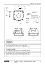
Page 21: ... air purge front 1 Dynamic pressure monitoring for jaw end position open 2 Air coupling in top jaw 1 3 Air coupling in top jaw 2 4 Dynamic pressure monitoring for jaw end position closed 5 Bottom connection for coolant drain or use for air purge 6 Bottom connection for lubrication one sided supply left 7 Bottom connection for lubrication one sided supply right 8 No use Hose free direct connection ...

Page 22: ...th locking screws item 23 When using the air purge via connection 5 the two sound absorbers V mustberemovedandreplacedbyset screws item 93 Accessory kit 36 Requirements for compressed air supply compressed air compressed air quality according to ISO 8573 1 7 4 4 Unconditioned compressed air contains dust and oil particles and moisture all of which can lead to malfunctions or premature wear in the ...

Page 23: ...ion Size 64 100 140 160 250 KTR KTR H KTR KTR H KTR KTR H KTR KTR H KTR KTR H B1 mm 4 5 4 5 14 14 18 5 18 5 28 28 36 36 B2 mm 18 18 35 35 46 5 41 5 56 51 80 75 T1 mm 11 30 18 43 27 62 30 70 35 85 T2 mm 4 23 9 34 15 50 19 59 21 71 ØC mm 2 2 2 2 2 D mm 7 3 6 6 5 20 E mm 3 5 5 5 1 1 1 F mm 2 0 1 2 0 1 2 0 1 2 0 1 2 5 0 1 Non tolerated dimensions according to DIN ISO 2768mH When using top jaws type ST...

Page 24: ...bserved Dynamic pressure monitoring of the workpiece flat work surface For this purpose the customer must provide the top jaw with a Ø2 mm monitoring hole on the workpiece flat work surface This ensures that the escaping air purge can be released up to where contact is made with the mounted workpiece and that a differential pressure measurement can be carried out via a differential pressure switch...

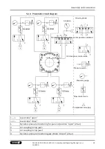
Page 25: ...irectional control valve center position ventilated 3 2 directional control valve Pressure switch Pressure gauge Flow control valve Compressed air supply Jaw stroke open Jaw stroke close 1 Dynamic pressure monitoring for jaw end position open 2 bar 2 Air coupling in top jaw 1 3 Air coupling in top jaw 2 4 Dynamic pressure monitoring jaw stroke closed 2 bar ...

Page 26: ...stem to SCHUNK for repair Piston rod or piston rod screw connection broken overload Send clamping system to SCHUNK for repair Active air connections sealed Remove set screws from sealed air connections Clamping force block does not complete stroke Possible cause Solution s Chips or dirt between covering strip and base jaws Unscrew the covering strip item 8 and remove chips and dirt Opening pressur...

Page 27: ...ositions do not work properly Possible cause Solution s Monitoring pieces in the base jaws not positioned exactly Readjust monitoring piece for the required function 7 28 Pressure change due to clamping stroke too low Adjust clamping stroke to the workpiece to 0 3 mm jaw Seals damaged Replacesealsincoverandadapter plate 8 1 35 ...

Page 28: ... spare parts Replacement of the housing and base jaws The base jaws and the guides in the housing are matched to each other To replace these parts send the entire product to SCHUNK with a repair order 7 2 Maintenance and lubrication intervals The following maintenance work should be carried out after the specified cycle numbers or at the latest according to the monthly data Maintenance work Interv...

Page 29: ...ith lubricants on the product In case of foreseeable contact with lubricants on the product e g when lubricating or cleaning wear protective equipment protective gloves protective goggles To maintain reliable function and high quality of the product it has to be regularly lubricated This can be done with a hand lever press for greases or by means of central lubrication Manual lubrication Press gre...

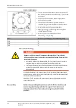
Page 30: ... life in case of improper disassembly The cylinder piston and the cover are under tremendous spring force which can eject the parts Any work requiring disassembly of the chuck piston cover or cylinder piston may only be performed by SCHUNK For basic cleaning only the base jaws with their attachments as well as the chuck piston and the cover strip may be dismantled For basic cleaning the upper part...

Page 31: ...ne table If using clamping sleeves 85 remove them from the housing Remove screws 64 and take off the cover strip 8 Remove screws 66 and take off the guide strip 6 Variant PM also includes a compression spring 27 O ring 43 sphere 24 and O ring 42 Remove the screw 69 Remove chuck piston 3 and base jaws 2 In the case of the PM variant note that the monitoring elements can fall off when the base jaws ...

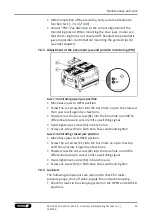
Page 32: ... adjusted and secured with the set screws 61 63 Caution The monitoring piece is under spring pre load and is installed directionally oriented for each base jaw See detail views for jaw 1 and jaw 2 Maintenance Clean all disassembled parts thoroughly and check fordamage and wear Treat all sliding surfaces with lubricant 7 3 29 Replace the seals of the monitoring if necessary 8 1 35 Assembly Assembly...

Page 33: ...w it again by a few turns Slowly screw the set screw 61 into the bore hole oo untilthe differential pressure sensor emits a switching signal Hand tighten set screw 61 in bore hole o Screw set screw 63 in both bore holes and hand tighten Jaw 2 monitoring closed jaw position Move base jaws to CLOSED position Screw the set screw 61 into the bore hole oo up to thestop and then unscrew it again by a fe...

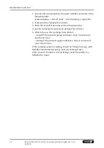
Page 34: ...e and remove the supply line 4 Let the clamping force block sit clamped for 24 hours 5 After 24 hours the clamping force block is sealed if the pressure gauge indicates a drop in pressureof less than 0 5 bar leaking if the pressure gauge indicates a drop in pressureof more than 0 5 bar If the clamping system is leaking check the fittings first e g with Metaflux leak detection spray Seal any leakin...

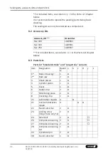
Page 35: ...d clamping force blocks KSF3 only the monitoring connection sealing kit provided by the customer is relevant 8 1 1 Piston chamber sealing kit The piston chamber seals should only be replaced by SCHUNK Danger to life in case of improper disassembly The sealing kit for the piston chamber contains all seals and wearing parts for the parts installed inside e g cylinder pistons Sealing kit ID number Si...

Page 36: ...8591 Size 250 1428597 For included items see column z in the Parts List chapter below 8 3 Parts lists Parts list Standard stroke and Long stroke variants Item Designation Quanti ty a b c d y z 1 Body Housing 1 2 Base jaw 2 3 Chuck piston 1 4 Cylinder piston 1 5 Cover 1 6 Guide strip 2 7 Monitoring piece 2 8 Covering strip 1 21 Lubrication nipples 4 21 Conical lubrication nipple 4 22 Sound absorber...

Page 37: ...screw 4 62 Set screw 10 63 Set screw 4 64 Countersunk screw ISO 14581 2 65 Countersunk screw 9 13 66 Cylindrical screw 2 69 Screw 1 70 Set screw 1 81 Plug 4 82 Fitting screw 2 83 O ring DIN ISO 3601 4 84 Screw 4 85 Clamping sleeve 2 86 Screw 8 87 O ring DIN ISO 3601 10 89 Set screw 2 93 Set screw 2 100 T handle 2 Parts list fixed jaw variant Item Designation Quanti ty a b c d y z 1 Body Housing 1 ...

Page 38: ...28 Compression spring set 1 34 Cylindrical pin 2 38 Sound absorber 1 40 Quad ring 1 41 Combined sealing ring 10 42 O ring DIN ISO 3601 2 43 O ring DIN ISO 3601 1 44 O ring DIN ISO 3601 2 45 O ring DIN ISO 3601 1 48 Flat seal 2 60 Set screw 2 61 Set screw 2 62 Set screw 10 63 Set screw 2 64 Countersunk screw 2 65 Countersunk screw 9 13 66 Cylindrical screw 1 67 Cylindrical screw 1 68 Cylindrical sc...

Page 39: ...01 10 89 Set screw 2 93 Set screw 2 100 T handle 2 Parts list key a for all sizes y wearing part b for size 100 included in the piston chamber sealing kit c for size 160 included in the monitoring sealing kit d for size 250 z included in accessory kit Individual components are specially tuned to one another and cannot be replaced by the customer ...

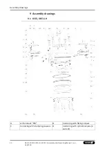
Page 40: ...3 F Assembly and Operating Manual en 1467140 Assembly drawings 9 Assembly drawings 9 1 KSF3 KSF3 LH A with variant PM B Centering with fitting screws C Centering with clamping sleeves D Centering with cylindrical pins Z variant ...

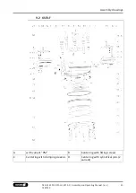
Page 41: ...SF3 LH KSF3 F Assembly and Operating Manual en 1467140 41 Assembly drawings 9 2 KSF3 F A with variant PM B Centering with fitting screws C Centering with clamping sleeves D Centering with cylindrical pins Z variant ...

Page 42: ...7389 1448302 1457400 1457402 1457403 1448304 1457405 1457407 1448305 1457413 1457393 1457394 1448298 1457395 1457397 1448295 1457398 1457430 1457399 1448297 1460101 The partly completed machine may not be put into operation until conformity of the machine into which the partly completed machine is to be installed with the provisions of the Machinery Directive 2006 42 EC is confirmed Applied harmon...

Page 43: ...448295 1457398 1457430 1457399 1448297 1460101 To be provided by the System Integrator for the overall machine Fulfilled for the scope of the partly completed machine Not relevant 1 1 Essential Requirements 1 1 1 Definitions X 1 1 2 Principles of safety integration X 1 1 3 Materials and products X 1 1 4 Lighting X 1 1 5 Design of machinery to facilitate its handling X 1 1 6 Ergonomics X 1 1 7 Oper...

Page 44: ... 1 4 2 Special requirements for guards X 1 4 2 1 Fixed guards X 1 4 2 2 Interlocking movable guards X 1 4 2 3 Adjustable guards restricting access X 1 4 3 Special requirements for protective devices X 1 5 Risks due to other hazards 1 5 1 Electricity supply X 1 5 2 Static electricity X 1 5 3 Energy supply other than electricity X 1 5 4 Errors of fitting X 1 5 5 Extreme temperatures X 1 45 6 Fire X ...

Page 45: ...ward 2 Supplementary essential health and safety requirements for certain categories of machinery X 2 1 Foodstuffs machinery and machinery for cosmetics or pharmaceutical products X 2 2 Portable hand held and or guided machinery X 2 2 1 Portable fixing and other impact machinery X 2 3 Machinery for working wood and material with similar physical characteristics X 3 Supplementary essential health a...

Page 46: ...SCHUNK ...

Page 47: ...SCHUNK ...

Page 48: ... GmbH Co Spanntechnik KG Lothringer Str 23 D 88512 Mengen Tel 49 7572 7614 0 Fax 49 7572 7614 1099 info de schunk com schunk com Folgen Sie uns I Follow us 01 2022 2022 SCHUNK GmbH Co KG 02 00 KSF3 KSF3 LH KSF3 F Assembly and Operating Manual en 1467140 ...

Reviews: