02.00 | KSH3 IM | Assembly and Operating Manual | en | 1477686
23
Assembly and connection
For the proper use of the proximity switches, observe the
following:
•
Do not pull forcefully on the sensor cable.
•
Do not subject the sensor cable to tensile strain.
•
Install the sensor connection cable straight and do not twist it.
•
Tighten the counter nut for clamping the sensor using a suitable
tool and moderate manual force.
•
Do not exceed the permissible bending radius of the cable (
☞
catalog specifications)
•
Position the sensor so that the signal LED on the sensor head is
clearly visible (with cover, LED is not visible).
•
Prevent the proximity switch from coming into contact with
hard objects or with chemicals; in particular, nitric, chromic or
sulfuric acid.
Proximity switches are electronic components which can react
sensitively to high-frequency interference or electromagnetic
fields.
•
Check that the cable is correctly connected and installed. There
must be sufficient distance between the switches and sources
of interference and their supply cables.
•
Parallel switching of multiple sensor outputs of the same design
(npn, pnp) is permissible, though this does not increase the
permissible load current.
•
Please note that the leakage current of the individual sensors is
accumulative (by about 2 mA).
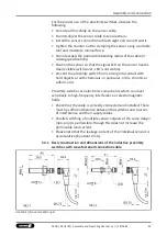
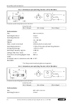
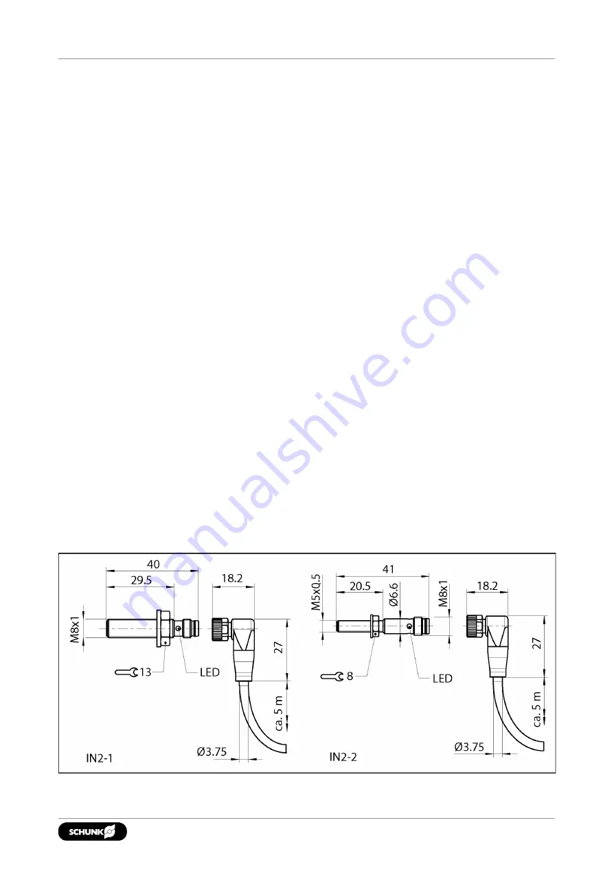
5.3.1
Basic construction and dimensions of the inductive proximity
switches with scew-fastened connection cable
IN S-M8-1 left and IN S-M8-2 right


