


26
02.00 | KSH3 IM | Assembly and Operating Manual | en | 1477686
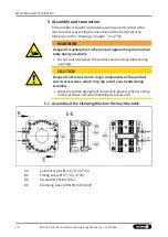
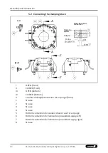
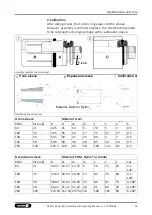
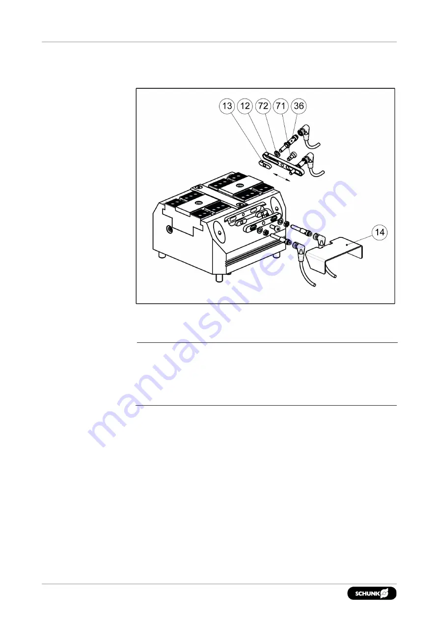
Assembly and connection
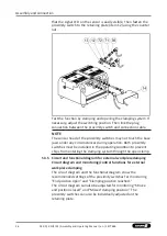
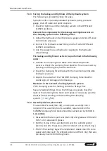
that the signal LED on the sensor is easily visible. Then fasten the
proximity switch to the retaining plate (item 12) using the counter
nut.
Test the function by clamping and opening the clamping system. If
necessary, adjust the switching position. Then link the plug
connection between the proximity switch and connection cable.
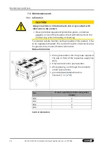
NOTE
The sensor head of the proximity switches may not touch the base
jaws under any circumstances during operation. Both proximity
switches must be installed in the operating condition to prevent
chips from entering the clamping system through the open clamp.
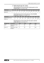
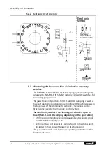
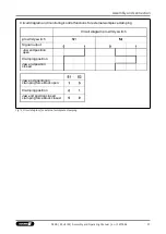
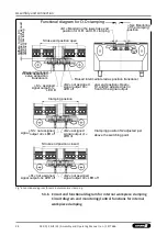
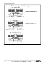
5.3.5
Circuit and functional diagram for external workpiececlamping
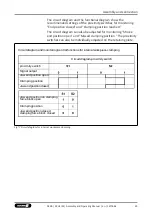
Circuit diagram and monitoring/control functions for external
workpiece clamping
The circuit diagram and the functional diagram show the
recommended settings of the proximity switches for monitoring
"End position open" and "Clamping position reached."
The circuit diagram can also be adjusted for monitoring "Stroke
end position closed" and "Missed clamping position." The
proximity switches can also be individually adjusted on the
retaining plate.


