


28
02.00 | KSH3 IM | Assembly and Operating Manual | en | 1477686
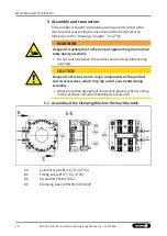
Assembly and connection
output »0« LED of
signal output »0« LE
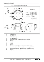
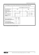
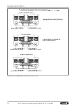
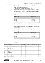
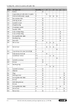
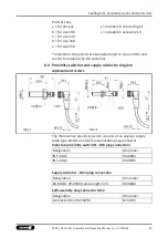
Functional diagram for O.D clamping
»S1« Monitoring the jaw stroke end
position for O.D. and I.D. clamping
»S2« Monitoring
of the clamping
position
Stroke end position open
Edges in front and
behind depression
serve asposition
transducers
Raised intermediate rail as position transducer
»S1« assigned
signal output »1«
LED lit
»S2« not assigned
signal output »0«
LED off
Jaw end position »Open«
S1 and S2 adjusted just in
front of the signal output
Clamping position
signal»S1« not assignedf
»S2« assigned
Clamping position S2 adjusted just
output »0« LED of
signal output »1«
LED lit
above the switching point
Stroke end position closed
signal»S1« not assignedf
»S2« not assigned
D off
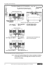
Fig.°6 Functional diagram for external workpiece clamping
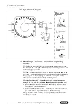
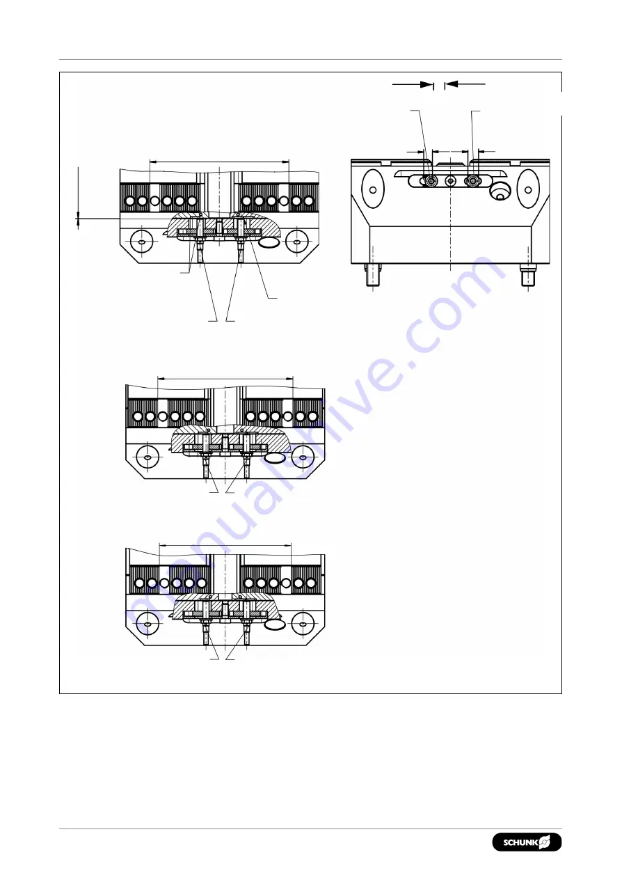
5.3.6
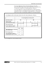
Circuit and functional diagram for internal workpiece clamping
Circuit diagram and monitoring/control functions for internal
workpiece clamping
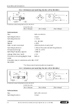
Adher
e t
o
m
in.
0
.3
di
st
anc
e
(do no
t ex
ceed
m
in
im
um
s
wit
ch
in
g
di
st
anc
e)


