
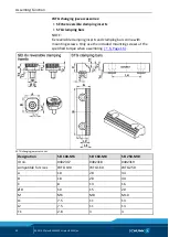
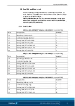
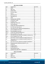
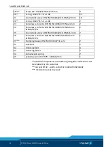
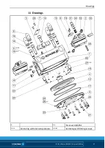
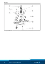
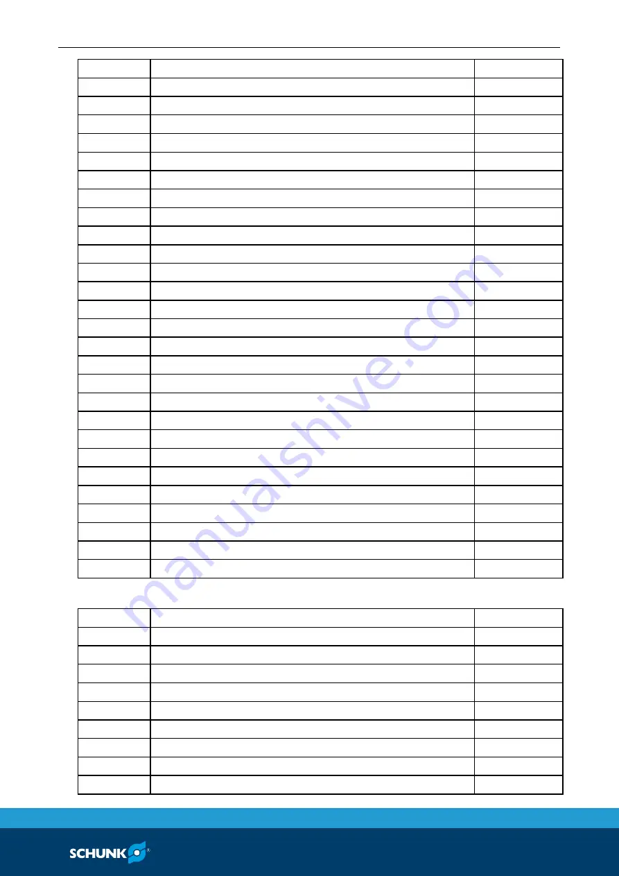
Seal Kit and Parts List
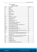
02.00|KSPplus-BWM KSP-LHplus-BWM |en
43
4
Cylinder piston
1
5
Cover
1
6
Covering strip
2
7
Covering strip
1
8***
Plug
4
9***
Fitting screw, 12f7/M10
2
10
Lubrication nipple
4
11
Locking screw
2
12**
Quad ring, 126.59 x 3.53
1
13
Sound absorber
1
14
Screw, DEI 4762/10.9 M10x25 mm
1
15**
Combined sealing ring
1
16
Countersink screw, DIN EN ISO 4026 M3x6 mm
4
17**
O-ring, DIN 3771 150 x 2.00
1
18***
O-ring, DIN 3771 12 x 2.00
4
19***
Screw, DEI 4762/10.9 M10x40 mm
4
20**
O-ring, DIN 3771 5.5 x 1.00
17
21
Countersink screw, DIN EN ISO 10642/10.9 M5x20 mm
15
22**
O-ring, DIN 3771 4.5 x 1.00
2
23
Set-screw, similar to DIN EN ISO 4026/45H M5x4 mm
4
25
Countersink screw, DIN EN ISO 10642/10.9 M5x10 mm
2
26
Set-screw, DIN EN ISO 4026/45H M4x4 mm IN6RD/VZ/PA 1
27***
Clamping sleeve, DIN EN ISO 13337 13 x 18
2
31
Lock bolt
2
32
Unlocking bolt
4
33
Unlocking bolt 2
2
34
Compression spring
2
35
Cylindrical pin, DEI 7979 - 5 M6x24 mm
1
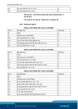
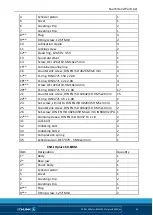
KSH-LHplus 160-BWM
Item
Designation
Quantity
1*
Body
1
2*
Base jaw
2
3*
Chuck body
1
4
Cylinder piston
1
5
Cover
1
6
Covering strip
2
7
Covering strip
1
8***
Plug
4
9***
Fitting screw, 12f7/M10
2


