Assembly
36
01.00|KSP3-IM, KSP3-LH-IM |en
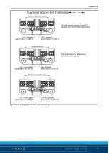
Circuit and functional diagram for internal workpiece clamping
Circuit diagram and monitoring/control functions for internal
workpiece clamping
The circuit diagram and the functional diagram show the
recommended settings of the proximity switches for monitoring
"End position closed" and "Clamping position reached."
The circuit diagram can also be adjusted for monitoring "Stroke
end position open" and "Missed clamping position." The proximity
switches can also be individually adjusted on the retaining plate.
Fig.°7 Circuit diagram for internal workpiece clamping
5.4.6


