background image

Maintenance and care 


40 

01.00|KSP3-IM, KSP3-LH-IM |en 


Maintenance and care 


Notes 

Original spare parts 

Only use original SCHUNK spare parts when replacing wearing 

parts/spare parts. 

Replacement of the housing and base jaws 

The base jaws and the guides in the housing are matched to each 

other. To replace these parts, send the entire product to SCHUNK 

with a repair order. 

Maintenance variant with clamping force maintenance (AS) 

The cylinder piston must be disassembled or assembled using a 

disassembly and assembly device. We therefore recommend you 

have maintenance work and change of seals performed at 

SCHUNK. 


Maintenance and lubrication intervals 

The following maintenance work should be carried out after the 

specified cycle numbers or, at the latest, according to the monthly 

data. 


Maintenance work 

Interval [cycles/months] 

Lubrication 

10000/1 

Basic cleaning 

-/6 

Leak test 

5000/1 


Regularly check inductive proximity switches for proper 

functioning. Check for damage to connection cables, connection 

plugs and the sensor head. 


7.1 

7.2 

Summary of Contents for TANDEM KSP3-IM

Page 1: ...Translation of Original Operating Manual TANDEM Clamping Force Block KSP3 IM KSP3 LH IM Assembly and Operating Manual Superior Clamping and Gripping...

Page 2: ...ed company the leading technology supplier of robots and production machines Our team is always available to answer any questions on this product and other solutions Ask us questions and challenge us...

Page 3: ...peration 12 2 10 Transport 12 2 11 Malfunctions 13 2 12 Disposal 13 2 13 Fundamental dangers 13 2 13 1 Protection during handling and assembly 14 2 13 2 Protection during commissioning and operation 1...

Page 4: ...36 6 Troubleshooting 38 7 Maintenance and care 40 7 1 Notes 40 7 2 Maintenance and lubrication intervals 40 7 3 Greasing areas lubricants 41 7 3 1 Lubrication 41 7 3 2 Leak test 48 7 3 3 Assembly dev...

Page 5: ...trations in this manual are provided for basic understanding and may differ from the actual product design In addition to these instructions the documents listed under 1 1 2 Page 6 are applicable Pres...

Page 6: ...0 000 cycles if it is used as intended under the following conditions Observe the applicable documents 1 1 2 Page 6 Observe the ambient conditions and operating conditions 2 6 Page 10 Observance of th...

Page 7: ...LH IM en 7 Accessories see catalog or data sheets when ordering separately Top jaw blanks type STR KTR Supporting jaws type TBA G TANDEM Base plates Valves pneumatic screws Extension cable for INW ind...

Page 8: ...nce with all instructions in this manual Not intended use The product is not being used as intended if for example It is used as lifting equipment as a press as a punching tool as a lathe chuck as a d...

Page 9: ...ts can endanger personnel and damage the product or cause it to malfunction Use only original spare parts or spares authorized by SCHUNK Use of special chuck jaws Requirements of the chuck jaws When u...

Page 10: ...sonnel working with the product is not sufficiently qualified the result may be serious injuries and significant property damage All work may only be performed by qualified personnel Before working wi...

Page 11: ...against danger which may interfere with their health or safety at work When working on and with the product observe the occupational health and safety regulations and wear the required personal protec...

Page 12: ...and maintenance instructions Observe the current safety accident prevention and environmental protection regulations regarding the product s application field IMPORTANT Following a longer shutdown pe...

Page 13: ...ing of disposal The incorrect handling of disposal may impair the product s safety and cause serious injuries as well as considerable material and environmental harm Follow local regulations on dispat...

Page 14: ...uitable assembly and transport equipment and take precautions to prevent jamming and crushing Incorrect lifting of loads Falling loads may cause serious injuries and even death Stand clear of suspende...

Page 15: ...t and the current operating condition of the drive Perform maintenance work modifications and attachments outside the danger zone defined by the movement range To avoid accidents and or material damag...

Page 16: ...o immediate closing of the product with high spring force in the event of pneumatic pressure failure AS variant Ensure stable compressed air supply Use pressure maintenance valves WARNING Risk of inju...

Page 17: ...rce Use load handling equipment for lifting and transporting CAUTION Allergic reactions or irritation due to skin or eye contact with lubricants on the product In case of foreseeable contact with lubr...

Page 18: ...t accuracy mm 0 01 0 01 0 01 0 02 Max jaw stroke mm 60 60 60 150 Weight kg 4 7 5 11 32 Designation KSP3 LH IM 100 140 160 250 Stroke per jaw mm 6 7 8 15 Clamping force at max pressure Standard AS vari...

Page 19: ...4 50 75 F 32 45 5 40 64 G 34 5 51 8 59 7 92 6 H 55 74 82 139 6 I 64 91 104 170 J 69 2 72 7 82 2 98 2 K 36 38 42 82 L 10 13 5 15 20 M 59 88 100 150 N M8 M8 M10 M12 O 15 15 5 18 20 P 4 3 5 4 5 Q 10f7 10...

Page 20: ...Technical data 20 01 00 KSP3 IM KSP3 LH IM en 1 Optional Z variant 0 01 mm to clamping center 2 Clamping sleeve 0 04 mm to clamping center 3 Clamping sleeve fitting screw 0 02 mm to clamping center...

Page 21: ...ening torques for mounting top jaws on the TANDEM clamping force block screw quality 12 9 Screw size M4 M5 M6 M8 M10 M12 M14 M16 M20 M24 Tightening torques MA Nm 5 9 15 32 62 108 170 262 510 880 Tight...

Page 22: ...ge 54 WARNING Danger of crushing due to the product approaching the machine table during assembly Do not reach between the product and machine table during assembly CAUTION Danger of abrasions due to...

Page 23: ...e base jaws item 2 in order to be able to align the clamping force block on the machine table or check the positioning Assembly with clamping sleeves Mount the clamping force block on the machine tabl...

Page 24: ...e accessory kit instead of the M8 x 35 screws item 84 For KSP3 160 IM KSP3 LH 160 IM Use the M10 x 35 screws from the base plate accessory kit instead of the M10 x 40 screws item 84 For KSP3 250 IM KS...

Page 25: ...quired minimum pressure NOTE The clamping force block is delivered with all four air connections sealed On the base side with set screws item 60 and on the front with locking screws item 23 When using...

Page 26: ...OPEN bottom IV CLOSED bottom V Coolant drainage connection for air purge front 1 No use 2 No use 3 No use 4 No use 5 Bottom connection for coolant drain or use for air purge 6 Bottom connection for lu...

Page 27: ...G1 8 NOTE The clamping force block is delivered with all four air connections sealed On the base side with set screws item 60 and on the front with locking screws item 23 When using the air purge via...

Page 28: ...om SCHUNK contact persons Technical data for the sensors can be found in the data sheets included in the scope of delivery or at schunk com The proximity switch used has reverse polarity protection an...

Page 29: ...between the switches and sources of interference and their supply cables Parallel switching of multiple sensor outputs of the same design npn pnp is permissible though this does not increase the perm...

Page 30: ...itching function Closer Switching distance 1 5 mm Voltage 10 30 V DC Ripple 15 Max current on contact 200 mA short circuit proof Switching hysteresis 15 of the nominal switching distance Temperature r...

Page 31: ...Switching function Closer Switching distance 1 5 mm Voltage 10 30 V DC Ripple 10 Max current on contact 100 mA short circuit proof Switching hysteresis 15 of the nominal switching distance Temperature...

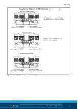
Page 32: ...a the signal output of switch S2 The function and circuit diagram for adjusting the proximity switches is shown in illustrations 6 7 and 8 The proximity switches are equipped with an LED signal displa...

Page 33: ...on Then link the plug connection between the proximity switch and connection cable NOTE The sensor head of the proximity switches may not touch the base jaws under any circumstances during operation B...

Page 34: ...am and the functional diagram show the recommended settings of the proximity switches for monitoring End position open and Clamping position reached The circuit diagram can also be adjusted for monito...

Page 35: ...Assembly 01 00 KSP3 IM KSP3 LH IM en 35 Fig 6 Functional diagram for external workpiece clamping...

Page 36: ...am and the functional diagram show the recommended settings of the proximity switches for monitoring End position closed and Clamping position reached The circuit diagram can also be adjusted for moni...

Page 37: ...Assembly 01 00 KSP3 IM KSP3 LH IM en 37 Fig 8 Functional diagram for internal workpiece clamping...

Page 38: ...CHUNK for repairs or disassemble clamping system and repair using original SCHUNK spare parts Piston rod or piston rod screw connection broken overload Send clamping system to SCHUNK for repairs or di...

Page 39: ...ck does not complete stroke Possible cause Solution s Chips or dirt between covering strip and base jaws Unscrew the covering strip item 8 and remove chips and dirt Clamping force getting weaker Possi...

Page 40: ...enance AS The cylinder piston must be disassembled or assembled using a disassembly and assembly device We therefore recommend you have maintenance work and change of seals performed at SCHUNK Mainten...

Page 41: ...so be used as an alternative to LINOMAX 200 However the specified clamping forces exclusively refer to the LINOMAX 200 used by SCHUNK For LINOMAX plus the clamping forces can be lower Lubrication CAUT...

Page 42: ...tervals 7 3 Page 41 Size Grease quantity strokes per grease nipple 100 2 140 2 160 2 250 3 Central lubrication To use central lubrication the set screws of the factory sealed connections 6 7 must be r...

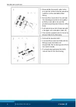
Page 43: ...ylinder pistons AS variant Only trained specialist personnel may disassemble the clamping force block The cover may only be removed with the aid of a suitable disassembly device For basic cleaning the...

Page 44: ...12 together with the cover item 14 and the proximity switches item 36 out of the body Each proximity switch is fastened with a hexagon nut and washer item 72 The counter supports item 13 can be disass...

Page 45: ...42 out of the housing To do this screw two screws into the threaded holes as an extraction tool for size 64 M3 x L 25 for size 100 M3 x L 25 for size 140 M4 x L 25 for size 160 M3 x L 25 for size 250...

Page 46: ...ton item 3 out of the housing via its extraction thread Push the cylinder piston together with the quad ring item 40 out of the housing Remove the combination sealing ring item 41 from the housing Var...

Page 47: ...rews in the cover can still be removed Remove screws item 65 and slowly open device until compression springs are released Remove the mounting cover item 200 compression springs item 28 combination se...

Page 48: ...and quick coupling Check for tightness in the clamping system in the OPEN and CLOSED positions 1 Connect the components to the open CLOSED connection in the following order Pressure gauge shut off val...

Page 49: ...160 250 d1 97 5 137 5 155 5 245 d2 79 118 135 219 d3 40 57 77 123 d4 10 12 12 12 d5 5 5 5 5 5 5 6 6 T1 5 6 5 8 5 10 5 T2 3 3 5 6 7 5 T3 1 8 3 4 1 5 A 38 9 45 5 39 93 8 B 38 9 36 49 8 93 8 C 43 5 63 5...

Page 50: ...parts that come into contact with the workpiece are not covered by the warranty Sealing kit lists Sealing kit ID Size 100 1470645 Size 140 1470642 Size 160 1470647 Size 250 1470648 For included items...

Page 51: ...6 Guide strip 2 8 Covering strip 1 12 Retaining plate 1 13 Counter support 2 14 Cover 1 21 Funnel lubrication nipple 4 21 Conical lubrication nipple 4 22 Sound absorber 2 23 Locking screw 2 28 Compres...

Page 52: ...82 Fitting screw 2 83 O ring DIN ISO 3601 4 84 Screw 4 85 Clamping sleeve 2 86 Screw 8 87 O ring DIN ISO 3601 10 89 Set screw 2 93 Set screw 2 100 T handle 2 Parts list key a for all sizes y included...

Page 53: ...IN consists of an angular supply cable type KA M12 and self assembly plug connector Inductive proximity switch IN M8 plug connection Designation ID number IN S M8 1 1349984 IN S M8 2 1349990 Supply ca...

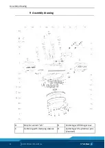
Page 54: ...Assembly drawing 54 01 00 KSP3 IM KSP3 LH IM en Assembly drawing A Only for variant AS B Centering with fitting screw C Centering with clamping sleeves D Centering with cylindrical pins Z variant 9...

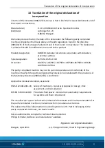
Page 55: ...67375 1467555 1467569 1467580 1467589 1467620 1467590 1467594 The partly completed machine may not be put into operation until conformity of the machine into which the partly completed machine is to b...

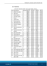
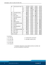
Page 56: ...l Systems 1 2 1 Safety and reliability of control systems X 1 2 2 Control devices X 1 2 3 Starting X 1 2 4 Stopping X 1 2 4 1 Normal stop X 1 2 4 2 Operational stop X 1 2 4 3 Emergency stop X 1 2 4 4...

Page 57: ...1 2 Warning devices X 1 7 2 Warning of residual risks X 1 7 3 Marking of machinery X 1 7 4 Instructions X 1 7 4 1 General principles for the drafting of instructions X 1 7 4 2 Contents of the instruct...

Reviews: