background image

Assembly 


32 

04.00|NSE plus, NSL plus, NSD plus |en 


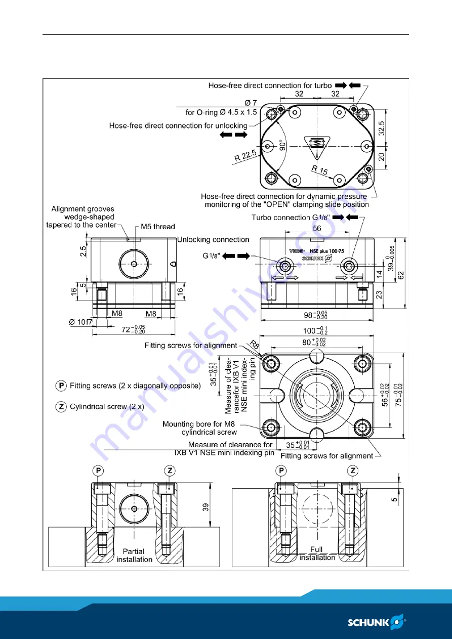
NSE plus 100-75 


4.3.10 

Summary of Contents for VERO-S NSE plus 100-75

Page 1: ...Translation of Original Operating Manual VERO S quick change pallet system NSE plus NSL plus NSD plus Assembly and Operating Manual Superior Clamping and Gripping ...

Page 2: ...ions for the purpose of technical improvement Document number 0489060 Version 04 00 05 03 2018 en H D SCHUNK GmbH Co All rights reserved Dear Customer thank you for trusting our products and our family owned company the leading technol ogy supplier of robots and production machines Our team is always available to answer any questions on this product and other solutions Ask us questions and challen...

Page 3: ...fication 10 2 7 Personal protective equipment 11 2 8 Notes on safe operation 12 2 9 Transport 12 2 10 Malfunctions 12 2 11 Disposal 13 2 12 Fundamental dangers 13 2 12 1 Protection during handling and assembly 13 2 12 2 Protection during commissioning and operation 14 2 12 3 Protection against dangerous movements 14 2 12 4 Notes on particular risks 15 3 Technical data 18 3 1 Special technical data...

Page 4: ...ions 48 4 6 1 Dynamic pressure monitoring of the clamping slide position for quick change pallet modules 48 4 6 2 Connecting strip ASL1 G1 8 ASL2 G1 8 50 4 7 Pneumatic circuit diagram 52 4 8 Screw tightening torques 53 5 Operation 54 6 Maintenance and care 55 7 Troubleshooting 56 7 1 The clamping area does not unlock 56 7 2 The clamping area does not unlock properly 56 7 3 The quick change pallet ...

Page 5: ...l Illustrations in this manual are provided for basic understanding and may differ from the actual product design In addition to these instructions the documents listed under 1 1 2 Page 6 are applicable Presentation of Warning Labels To make risks clear the following signal words and symbols are used for safety notes DANGER Danger for persons Non observance will inevitably cause irreversible injur...

Page 6: ... Clamping station NSL plus 150 NSL plus 150 V1 NSL plus 150 V1 T NSD plus 150 NSL plus 200 NSL plus 200 V1 T NSD plus 200 NSL plus 400 NSL plus 600 NSL plus 800 Warranty The warranty period is 24 months after delivery date from factory or 500 000 cycles if it is used as intended under the following conditions Observe the applicable documents 1 1 2 Page 6 Observe the ambient conditions and operatin...

Page 7: ...ver caps 6 mounting screws M8 NSE plus 100 75 3 O rings Ø 4 5 x 1 5 4 cover caps 4 mounting screws M8 Clamping station in the version ordered Accessory pack and separate packing units NSL plus 150 2 cylindrical clamp blanks BRR 50 NSL plus 150 V1 1 sealing ring G1 8 1 sealing nipple G1 8 1 pneumatic plug in connection for nominal hose width Ø 4 2 cy lindrical clamp blanks BRR 50 NSL plus 150 V1 T ...

Page 8: ... hose width Ø 6 2 eye bolts M8 6 cylindrical clamp blanks BRR 50 NSL plus 800 1 sealing ring G1 8 1 sealing nipple G1 8 1 pneumatic plug in connection for nominal hose width Ø 6 2 eye bolts M8 8 cylindrical clamp blanks BRR 50 Accessories see catalog or data sheets when ordering separately Clamping pallets PAL Clamping pins SPA SPB SPC SPG Connecting strip ASL1 G1 8 ASL2 G1 8 BRR clamping ring Ass...

Page 9: ...le It is used as a pressing tool a chuck a load handling device or as lifting equipment It is used for turning applications without consulting SCHUNK It is used in working environments that are not permissible People work on machines or technical equipment that do not comply with the EC Machinery Directive 2006 42 EC disregard ing the applicable safety regulations The technical data specified by t...

Page 10: ...t is a sufficient size for the applica tion Make sure that the contact surfaces of the interface are always clean Make absolutely sure that no chips of any kind can enter the in terface and that the interface does not fill with cooling emul sion which is particularly possible with vertical positioning of the clamping pin axis The best way to ensure both of these is to use the SDE protection covers...

Page 11: ...rator about the del egated tasks and possible dangers due to improper behaviour Due to its technical training knowledge and experience service personnel of the manufacturer is able to perform the delegated tasks and to recognize and avoid possible dangers Personal protective equipment Using personal protective equipment Not wearing personal protective equipment while working with the product may r...

Page 12: ... environ mental protection regulations regarding the product s applica tion field Transport Handling during transport Incorrect handling during transport may impair the product s safe ty and cause serious injuries and considerable material damage When handling heavy weights use lifting equipment to lift the product and transport it by appropriate means Secure the product against falling during tra...

Page 13: ...ergy supply is connected do not move any parts by hand Do not reach into the open mechanism or movement area of the product during operation Protection during handling and assembly Incorrect handling and assembly Incorrect handling and assembly may impair the product s safety and cause serious injuries and considerable material damage Have all work carried out by appropriately qualified personnel ...

Page 14: ...led monitors become effective it must be assumed that the drive movement is faulty with its ac tion being dependent on the control unit and the current oper ating condition of the drive Perform maintenance work modi fications and attachments outside the danger zone defined by the movement range To avoid accidents and or material damage human access to the movement range of the machine must be rest...

Page 15: ...t loosening of the clamping pin must be prevented using suitable countermeas ures disconnecting the power supply after locking use of check valves or safety switches The machines and equipment must fulfill the minimum re quirements of the EC Machinery Directive 2006 42 EC specif ically they must have effective technical measures to protect against potential mechanical hazards Wear personal protect...

Page 16: ...jury due to impurities e g metal chips in the exhaust and air purge connections of the clamping station Take appropriate protective measures to secure the danger zone Wear personal protective equipment safety goggles CAUTION Risk of injury due to compressed air hoses coming loose when connected improperly Use check valves or safety switches Take appropriate protective measures to secure the danger...

Page 17: ...he safety and accident prevention regulations when operating the quick change pallet system especially when working with machine tools and other technical equipment CAUTION Risk of burns due to workpieces with high temperatures There is a risk of burns due to workpieces with high tempera tures Wear protective gloves when removing workpieces Automatic loading is preferred CAUTION Danger due to pneu...

Page 18: ... 75 kN 75 kN 6 0 kN 20 kN NSE plus 176 0471060 35 kN 50 kN 75 kN 75 kN 9 0 kN 40 kN NSE plus 176 V1 0471096 35 kN 50 kN 75 kN 75 kN 9 0 kN 40 kN NSE plus 100 75 0471130 30 kN 50 kN 75 kN 4 0 kN 14 kN Holding force when fastening the clamping pin with cylindrical screw DIN EN ISO 4762 12 9 Actuation pressure 6 bar Repeatability mm 0 005 mm Installation position Any Operating temperature 15 C up to ...

Page 19: ... 300 A up to 600 A Gas flow rate 4 0 l min Tested protective gas type Corgon 18 82 Argon 18 CO2 Before initial start up please make sure that the machine plant where the Quick Change Pallet System should be integrated to complies with the stipulations of the EC machinery directives Please contact your contact person at SCHUNK if you intend to use the Quick Change Pallet System for any application ...

Page 20: ... this reason do not use this installation position Damage to the clamping module is possible Installing and connecting WARNING Risk of injury due to unexpected movements If the power supply is switched on or residual energy remains in the system components can move unexpectedly and cause seri ous injuries Before starting any work on the product Switch off the power supply and secure against restar...

Page 21: ...irection SPB 40 should be used for clamping systems that are more than 50 mm apart or that do not show a positioning tol erance of 0 01 mm For the clamping areas that are not intended for alignment of the device or pallet clamping pins with centering clearance SPC 40 can be used also refer to chapter Clamping pins 4 5 Page 46 Air bleed screw for the piston chamber When connecting the quick change ...

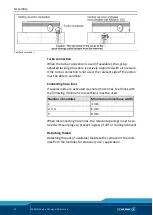
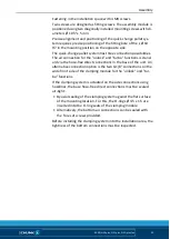
Page 22: ... to ventilate Connecting hose lines If several units are activated via shared hose lines feed lines with the following minimum cross sections must be used Number of modules Minimum nominal hose width 1 4 mm 2 3 4 6 mm 5 8 mm When disconnecting hose lines the relevant openings must be se cured with seal plugs to prevent ingress of dirt or cooling lubricant Detaching thread Detaching threads if avai...

Page 23: ...mbly module is positioned using the centering diameter of the installation space Ø 90H6 The air connection is normally made via the coupling holes in the floor of the unit Alternative connection option two G1 8 connections on the side In this case the bottom openings must be sealed off with the two M4 x 4 set screws 4 3 1 ...

Page 24: ...mbly module is positioned using the centering diameter of the installation space Ø 90H6 The air connection is normally made via the coupling holes in the floor of the unit Alternative connection option two G1 8 connections on the side In this case the bottom openings must be sealed off with the two M4 x 4 set screws 4 3 2 ...

Page 25: ...ith a fitting screw with a diameter of Ø 7 f7 x 3 mm Precise alignment and positioning of the quick change pallet sys tem requires precise positioning of the fitting bore Ø 7 H7 in the mounting positionon on the opposite side The air connection is normally made via the coupling holes in the floor of the unit Alternative connection option two G1 8 connections on the side In this case the bottom ope...

Page 26: ... H6 in the upper range Ø 110 H6 in the lower range depending on the installation type The air connection is normally made via the coupling holes in the floor of the unit Alternative connection option a side G1 8 connection which is free when using the bottom centering diameter 110H6 In this case the bottom opening must be sealed Either by inserting the O ring Ø 9 x 1 5 and applying to a flat versi...

Page 27: ...th a fitting screw with a diameter of Ø 9 f7 x 5 mm Precise alignment and positioning of the quick change pallet sys tem requires precise positioning of the fitting bore Ø 9 H7 in the mounting position on the opposite side The air connection is normally made via the coupling holes in the floor of the unit Alternative connection option a side G1 8 connection which is free when using the bottom cent...

Page 28: ...ositioned by means of two different centering diameters of the installation space Ø 138 H6 in the upper range Ø 110 H6 in the lower range depending on the installation type The air connection is normally made via the coupling holes in the floor of the unit The air connection is normally made via the coupling holes in the floor of the unit 4 3 6 ...

Page 29: ...H6 in the upper range Ø 110 H6 in the lower range depending on the installation type The exact position orientation is done with a cylindrical pin with a diameter of Ø 6 m6 x 11 mm Precise alignment and positioning of the quick change pallet sys tem requires precise positioning of fitting bore Ø 6 F7 in the mounting position on the opposite side The air connection is normally made via the coupling...

Page 30: ...6H6 in the upper range Ø 138H6 in the lower range depending on the installation type The air connection is normally made via the coupling holes in the floor of the unit Alternative connection option a side G1 8 connection which is free when using the bottom centering diameter 138H6 In this case the bottom opening must be sealed Either by inserting the O ring Ø 9 x 1 5 and applying to a flat versio...

Page 31: ...ew with a diameter of Ø 9 f7 x 5 mm Precise alignment and positioning of the quick change pallet sys tem requires precise positioning of the fitting bore of the Ø 9 H7 on the opposite side is precisely positioned in the mounting posi tion The air connection is normally made via the coupling holes in the floor of the unit Alternative connection option a side G1 8 connection which is free when using...

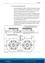
Page 32: ...Assembly 32 04 00 NSE plus NSL plus NSD plus en NSE plus 100 75 4 3 10 ...

Page 33: ...ions is stand ard via the hose free direct connections in the base of the unit An alternative connection option is the two G1 8 connections on the wide front side of the clamping module for the unlock and tur bo functions If the clamping system is actuated on the side connections using hoselines the base hose free direct connections must be sealed air tight By axial sealing of the clamping system ...

Page 34: ...aranteed when clamped The clamping station is fastened using the supplied BRR 50 clamping clips See the clamping dia gram for the arrangement of the BRR 50 clamping clips Clamping diagram Clamping range NSL plus 150 NSD plus 150 NSL plus 200 NSD plus 200 NSL plus 400 NSL plus 600 NSL plus 800 A I B C J K B E J M B D G J L O B D F H J L N P Mounting clamp blanks 4 4 ...

Page 35: ... 150 each have a G 1 8 air connection A plug in connection for nominal hose width 4 mm is contained in the scope of delivery of the NSL plus 150 and NSD plus 150 The NSL plus 150 clamping station can be retrofitted at the air connec tion with a separately available connecting strip chapter connect ing strip 4 6 2 Page 50 to increase the accessibility of the connection points With the NSD plus 150 ...

Page 36: ...ple are contained in the scope of delivery of the NSL plus 150 V1 Two plug in connections for nominal hose width 4 mm and two sealing nipples are contained in the scope of delivery of the NSL plus 150 V1 T The sealing nipple is compatible with common locking couplings NW 7 4 The right sealing coupling is available as an accessory The clamp ing station can be retrofitted at the two air connections ...

Page 37: ...G 1 8 connections the NSD plus 200 has two G 1 4 connections The connections are each connected with each other each connection supplies both clamping areas The air supply can be connected to either the front or the back of the clamping station The opposing connection point must be closed with the locking screw A pneumatic plug in connection for nominal hose width 4 mm and a sealing nipple are con...

Page 38: ...point It is possible to use single clamping pallets on the NSD plus 200 by installing a dome shaped centering bushing ZKA 12 Should the application require the separate control of the clamping areas both connections can be separated from each other by installing a G 1 8 sealing plug To separate the air systems the G 1 8 sealing plug is inserted about 80 mm into the supply bore hole and screwed int...

Page 39: ...onnec tions are connected with each other each connection supplies both clamping areas Two pneumatic plug in connections for nominal hose width 4 mm and two sealing nipples are contained in the scope of delivery of the NSL plus 200 The sealing nipple is compatible with common locking couplings NW 7 4 The right sealing coupling is available as an accessory The clamp ing station can be retrofitted w...

Page 40: ...g all four clamping points The air supply can either be connected on the front or the back of the clamping station while the opposing connecting point remains closed with a locking screw A pneumatic plug in connection for nominal hose width 6 mm and a sealing nipple are contained in the scope of delivery The sealing nipple is compatible with common locking couplings NW 7 4 The right sealing coupli...

Page 41: ...Assembly 04 00 NSE plus NSL plus NSD plus en 41 NSL plus 400 ...

Page 42: ...g all six clamping points The air supply can either be connected on the front or the back of the clamping station while the opposing connecting point remains closed with a locking screw A pneumatic plug in connection for nominal hose width 6 mm and a sealing nipple are contained in the scope of delivery The sealing nipple is compatible with common locking couplings NW 7 4 The right sealing couplin...

Page 43: ...Assembly 04 00 NSE plus NSL plus NSD plus en 43 NSL plus 600 ...

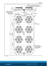
Page 44: ...g points The air supply can either be connected on the front or the back of the clamping station while the opposing connecting point remains closed with a locking screw A pneumatic plug in connection for nominal hose width 6 mm and a sealing nipple are contained in the scope of delivery The sealing nipple is compatible with common locking couplings NW 7 4 The right sealing coupling is available as...

Page 45: ...Assembly 04 00 NSE plus NSL plus NSD plus en 45 NSL plus 800 ...

Page 46: ...ck mounting material The clamping pins can be attached in two different ways to the workpiece or pallet the mounting variants are numbered in order of preference If clamping pins are used outside of SCHUNK pallets for example in customer specific devices or workpieces the outer diameter of the part to be clamped must be large enough to completely cover the O ring on the top of the quick change pal...

Page 47: ...40 0471153 12 17 M12 15 20 M10 15 12 SPG 40 0471154 12 17 M12 15 20 M10 25 22 SPA 40 16 0471064 13 18 M16 18 24 M12 20 16 SPB 40 16 0471065 13 18 M16 18 24 M12 20 16 SPC 40 16 0471066 13 18 M16 18 24 M12 20 16 The length of the screwed thread must not exceed the di mension G under any circumstances Usage arrangement of the different types of clamping pins Application pallet with 6 clamping positio...

Page 48: ...1 NSE plus 176 NSE plus 176 V1 and NSE plus 100 75 dynamic pressure monitor ing of the clamping slide is possible Pressure build up in OPENED status Control of the clamping slide monitor requires a reduced pressure supply limited to 2 bar see chapter Pneumatic circuit diagram 4 7 Page 52 The measurable differential pressure must reach a minimum of 0 5 bar in order for a reliable evaluation to be d...

Page 49: ...Assembly 04 00 NSE plus NSL plus NSD plus en 49 NSE plus 138 NSE plus 138 V1 NSE plus 176 NSE plus 176 V1 ...

Page 50: ...air can escape rapidly through a sound absorber The valve strip is available in two different versions a single connecting strip type ASL1 G1 8 and a coupled 2x connecting strip type ASL2 G1 8 To mount the connecting strip the front air connection sealing nipple is removed from the clamping station and in its place the connecting strip is directly adjusted via the hollow screw The rear air connect...

Page 51: ...ns NSL plus 150 V1 T installed 2x NSL plus 200 NSL plus 400 NSL plus 600 NSL plus 800 NSL plus 150 V1 T retrofitted with 1x connecting strip ASL1 G1 8 option 2x connecting strip ASL2 G1 8 ID no 1315007 suitable for clamping station NSL plus 200 V1 T NSL plus 200 V1 T retrofitted with 2x connecting strip ASL2 G1 8 Option ...

Page 52: ...bo function The actuating pressure for the turbo function must not exceed 6 bar Feeder query The max pressure of the feeder query is 2 bar Limit volumetric flow to 15 l min Pressure difference upon failure of a module min 1 bar If the feeder query of several standard NSE plus modules is connected in series only the evaluation of the OPEN position works dynamic pressure all modules open 4 7 ...

Page 53: ...incorrect measurement results The length and cross section of the line can affect the switching time of the control components It may be necessary to readjust the control components Check the control components of the monitoring functions at regular intervals If errors occur in the monitoring control system you must detect the cause of the error Screw tightening torques Tightening torques for moun...

Page 54: ...riginal SCHUNK spare parts may be used WARNING Risk of injury due to losing pallets or workpieces in the case of incorrect actuation caused by incorrect operation Risk of injury due to compressed air hoses coming loose when connected improperly Disconnect the energy supply after locking Use check valves or safety switches The danger zone must be surrounded by a protective enclo sure during operati...

Page 55: ... tool and by observing the corresponding disassembly and assembly instructions To ensure the quick change pallet system operates perfectly the following instructions are to be observed Pressure medium Compressed air compressed air quality accord ing to ISO 8573 1 7 4 4 NOTICE A separate maintenance unit with oiler must be used for the air supply Check the units at regular intervals at least every ...

Page 56: ...perly Possible cause Remedial measures Pressure below minimum Check operating pressure min 5 bar The module was not operated with oiled compressed air Install maintenance unit with oiler Hose diameter below minimum Required hose diameters see chapter Secur ing and connecting 4 3 Page 21 The turbo connection is still pressurized Ventilate the connection The quick change pallet system no longer open...

Page 57: ...er 1 NSE plus 99 NSE plus 99 V1 ID no 0471122 Item Designation Quantity 20 O ring Ø 71 5 x 1 5 1 21 O ring Ø 62 x 3 1 22 O ring Ø 26 x 1 5 1 23 O ring Ø 20 x 1 5 4 24 O ring Ø 4 5 x 1 5 2 25 O ring Ø 18 x 2 1 26 O ring Ø 71 5 x 1 5 2 27 O ring Ø 18 x 1 5 1 40 Slide washer 1 NSE plus 138 NSE plus 138 V1 ID no 0471052 Item Designation Quantity 20 O ring Ø 82 x 3 1 21 O ring Ø 96 x 3 2 22 O ring Ø 25...

Page 58: ...her 1 NSE plus 176 NSE plus 176 V1 ID no 0471225 Item Designation Quantity 19 O ring Ø 62 x 3 1 20 O ring Ø 96 x 3 1 21 O ring Ø 122 x 3 1 22 O ring Ø 25 x 3 1 23 O ring Ø 20 x 1 5 4 24 O ring Ø 9 x 1 5 3 25 O ring Ø 18 x 2 5 1 26 O ring Ø 112 x 1 5 1 27 O ring Ø 19 x 1 1 40 Slide washer 1 NSE plus 100 75 ID no 0471132 Item Designation Quantity 23 O ring Ø 4 5 x 1 5 3 24 O ring Ø 3 5 x 1 1 25 O ri...

Page 59: ...Set screw 3 36 Set screw 2 NSE plus 99 ID no 0471120 Item Designation Quantity 1 Base body 1 2 Cover 1 3 Clamping slide 2 4 Piston 1 6 Plug 1 30 Cylindrical screw 6 31 Cylindrical pin 2 32 G1 8 locking screw 2 33 Compression spring 12 36 Set screw 2 37 Set screw 3 45 Cover caps 6 NSE plus 99 V1 ID no 0471125 Item Designation Quantity 1 Base body 1 2 Cover 1 3 Clamping slide 2 4 Piston 1 6 Plug 1 2...

Page 60: ...Plug 1 19 Ring cord 1 30 Cylindrical screw 6 31 Cylindrical pin 2 32 G1 8 locking screw 2 33 Compression spring 8 35 Set screw 1 36 Set screw 2 45 Cover caps 6 NSE plus 138 V1 ID no 0471095 Item Designation Quantity 1 Base body 1 2 Cover 1 3 Clamping slide 2 4 Piston 1 6 Plug 1 19 Ring cord 2 29 Fitting screw PSC NSE PLUS 138 V1 1 30 Cylindrical screw 6 31 Cylindrical pin 2 32 G1 8 locking screw 2...

Page 61: ... 45 Cover caps 6 NSE T plus 138 V1 ID no 0471076 Item Designation Quantity 1 Base body 1 2 Cover 1 3 Clamping slide 2 4 Piston 1 6 Plug 1 30 Cylindrical screw 6 31 Cylindrical pin 2 32 Set screw 2 33 Compression spring 10 35 Set screw 1 36 Cylindrical pin 1 45 Cover caps 6 NSE plus 176 ID no 0471060 Item Designation Quantity 1 Base body 1 2 Cover 1 3 Clamping slide 2 4 Piston 1 6 Plug 1 30 Cylindr...

Page 62: ...ical screw 5 31 Cylindrical pin 2 32 G1 8 locking screw 2 33 Compression spring 8 35 Set screw 1 36 Set screw 2 45 Cover caps 6 NSE plus 100 75 ID no 0471130 Item Designation Quantity 1 Base body 1 2 Clamping slide 2 3 Piston 1 4 Cover 1 5 Bearing bracket for cylindrical pin 2 6 Fitting screw NSE plus 100 75 2 7 Cover caps 4 9 Compression spring 8 19 Countersunk screw 6 20 Cylindrical screw 2 21 G...

Page 63: ...Assembly Drawings 04 00 NSE plus NSL plus NSD plus en 63 Assembly Drawings NSE plus cylindrical version for NSE plus 99 NSE plus 138 NSE T plus 138 and NSE plus 176 9 9 1 ...

Page 64: ...Assembly Drawings 64 04 00 NSE plus NSL plus NSD plus en NSE plus V1 cylindrical version 9 2 ...

Page 65: ...Assembly Drawings 04 00 NSE plus NSL plus NSD plus en 65 NSE plus 100 75 9 3 ...

Page 66: ...er 0471059 0471120 0471125 0471150 0471095 0472100 0472105 0471076 0471077 0471060 0471096 0471130 0471045 0471046 0472210 0471047 0471044 0471003 0472220 0471002 0471048 0472240 0471082 0471083 0471570 0471571 0471540 0471541 The partly completed machine may not be put into operation until conformity of the ma chine into which the partly completed machine is to be installed with the provisions of...

Page 67: ...570 0471571 0471540 0471541 To be provided by the System Integrator for the overall machine Fulfilled for the scope of the partly completed machine Not relevant 1 1 Essential Requirements 1 1 1 Definitions X 1 1 2 Principles of safety integration X 1 1 3 Materials and products X 1 1 4 Lighting X 1 1 5 Design of machinery to facilitate its handling X 1 1 6 Ergonomics X 1 1 7 Operating positions X 1...

Page 68: ...1 6 5 Cleaning of internal parts X 1 7 Information 1 7 1 Information and warnings on the machinery X 1 7 1 1 Information and information devices X 1 7 1 2 Warning devices X 1 7 2 Warning of residual risks X 1 7 3 Marking of machinery X 1 7 4 Instructions X 1 7 4 1 General principles for the drafting of instructions X 1 7 4 2 Contents of the instructions X 1 7 4 3 Sales literature X The classificat...

Reviews: