background image

Maintenance and care 


20 

02|NSE-M plus 138 |en 


Maintenance and care 

The Quick Change Pallet System is designed for minimum-

maintenance operation, so that opening and disassembly of the 

clamping modules is only necessary in exceptional cases. 

If it is necessary to disassemble the quick change pallet system, 

this may only be performed by trained specialist personnel.


  •  Clean all parts thoroughly and check for damage and wear. 

Damaged and worn parts must be replaced. 

  •  Grease the sliding surfaces of the guide curves in the drive 

piston with LINO MAX 200. 

  •  Grease the sliding surfaces of all movable components with 

Renolit HLT 2. 

Replace damaged parts only with original SCHUNK replacement 

parts!


A repeated functional check is to be conducted before the start-

up. 


General operating conditions 

  •  Make sure that the bearing surface of the interface is always 

clean. 

  •  Please arrange the necessary, so that chips of any type can’t 

get into the interface. Moreover, please avoid that coolant 

emulsion fills up in the interface, espacially if the axis of the 

clamping pin is vertically aligned. Both can be avoided by using 

a protection cover SDE 138. 

If the interface should nevertheless fill with coolant emulsion, 

start locking and dry the interface during actuation. 

  •  For operation, only high-quality coolant emulsions with rust-

protection additions should be used. 

  •  Regularly inspect the units (at least every 2 weeks or after 1000 

clamping cycles). Perfect operation is given whenever the 

clamping slides move smoothly without increased application 

of force when actuated by means of the piston. Safe operation 

also includes the self-locking of the clamping area. 

  •  Regularly inspect the system visually and control proper 

function. In case of visible damages or signs of malfunction, 

please stop the operation immediately. The system should not 

be started up again, before all the damages are repaired. I.e. by 

exchanging the damaged unit. 

Summary of Contents for VERO-S NSE plus 138

Page 1: ...Translation of original operating manual VERO S Quick Change Pallet System NSE M plus 138 Assembly and Operating Manual Superior Clamping and Gripping ...

Page 2: ...company the leading technology supplier of robots and production machines Our team is always available to answer any questions on this product and other solutions Ask us questions and challenge us We will find a solution Best regards Your SCHUNK team H D SCHUNK GmbH Co Spanntechnik KG Lothringer Str 23 D 88512 Mengen Tel 49 7572 7614 0 Fax 49 7572 7614 1099 info de schunk com schunk com Customer M...

Page 3: ...s attachments or modifications 8 2 5 Personnel qualification 8 2 6 Organizational measures 9 3 Warranty 10 4 Scope of delivery 10 5 Technical data 10 6 Assembly 11 6 1 General assembly notes 11 6 2 Mounting and actuation 12 6 3 Clamping station optional 14 6 4 Clamping pins SPA 40 SPB 40 SPC 40 SPG 40 15 6 4 1 Information to clamping pin SPG 40 17 7 Function 18 7 1 Unlocking the clamping system 18...

Page 4: ...specially the chapter Basic safety notes Presentation of Warning Labels To make risks clear the following signal words and symbols are used for safety notes DANGER Danger for persons Non observance will inevitably cause irreversible injury or death WARNING Dangers for persons Non observance can lead to irreversible injury and even death CAUTION Dangers for persons Non observance can cause minor in...

Page 5: ...f the product is passed on to a third party these instructions must also be passed on Intended use This product is intended for positioning and clamping of clamping pallets or workpieces This product may only ever be employed within the restrictions of its technical specifications The requirements of the applicable directives must be observed and complied with The product is intended for industria...

Page 6: ... down of the fixture or pallet or not allowed overhead application Overhead application is not allowed since the clamping area is not secured by a spring Use a crane or a transport trolley during transport In case of horizontal application secure the fixture or pallet against falling down during loosening the clamping modules WARNING Risk of injury to persons due to falling down of the fixture pal...

Page 7: ...on The product may pose a danger to persons risk of injury and property if for example it is used other than as intended it is not installed or maintained properly the safety and installation instructions the safety and accident prevention regulations valid at the usage site or the EC Machinery Directive are not observed Maintenance instructions The maintenance and servicing intervals must always ...

Page 8: ... threads bore holes or attachments which are not supplied as accessories by SCHUNK may affect safety They may only be applied after obtaining the prior consent of SCHUNK Personnel qualification The Quick Change Pallet System must only be installed removed started up operated and serviced by qualified specialist personnel with the relevant safety training All persons charged with operating maintain...

Page 9: ...rds Hazard Notices The business operator must ensure that the notes of safety and hazards for the machine to which the Quick Change Pallet System is mounted are observed and that the notice signs are clearly legible Troubles If troubles occur at the system which could affect safety or production characteristics indicate that faults are in existence the machine to which the system is mounted must b...

Page 10: ...of delivery Quick Change Pallet System NSE M plus 138 Assembly and Operating Manual Enclosed pack 6 Covering caps 6 Fastening screws M8 Accessories Clamping pallets Type PAL Clamping pins Types SPA SPB SPC SPG Dome shaped centering bushing Type ZKA Protection cover Type SDE Fitting bolt PBN Spanner wrench Technical data NSE M plus 138 Id No 0471140 Retenion force M10 M12 M16 35 kN 50 kN 75 kN Pull...

Page 11: ...isk of injury due to squeezing Install the Quick Change Pallet System carefully Don t get your limps in a gap between moving parts or clamping fixture of the machine General assembly notes If several clamping units are to be mounted in serial connection please make sure that the evenness and deviation in height of the supporting surfaces from module to module keeps within 0 01 mm relating to a dep...

Page 12: ...02 NSE M plus 138 en Mounting and actuation If you wish to install the unit yourself please request our drawing The NSE M plus 138 is fastened in the installation area with six screws M8 Dimensions and assembly 6 2 ...

Page 13: ...piston is easy to access at all times An access bore of sufficient size ensures that the access to the hexagon socket is well visible If any chips are in the access bore or hexagon socket they have to be removed prior to actuation The clamping system is driven manually by rotating the drive piston item 4 The drive piston is laterally in the base body item 1 The drive piston item 4 is actuated with...

Page 14: ...ionally equipped with manually actuated quick change pallet modules The quick change pallet modules can be arranged and distributed as desired The arrangement of conventional modules for stationary use is illustrated in fig Clamping station Reliable access to the actuating piston must be ensured by the arrangement of the modules which applies in particular to adapted clamping pallets 6 3 ...

Page 15: ...of the screw connection which connects the clamping pin to the pallet or the device This is why only screws of strength class 12 9 may be used Only original SCHUNK clamping pins may be used If the clamping pins are to be used in customer owned devices the customer must provide sufficiently dimensioned threaded holes or a sufficiently thick mounting material The clamping pins can be fastened onto t...

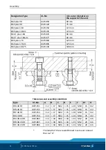
Page 16: ... NSE plus 176 V1 0471096 125 mm NSE plus 100 75 0471130 100 mm Tolerances and assembly conditions Type Id No A B C D E F G H SPA 40 RF 0471151 12 17 M12 15 20 M10 15 12 SPB 40 RF 0471152 12 17 M12 15 20 M10 15 12 SPC 40 RF 0471153 12 17 M12 15 20 M10 15 12 SPG 40 RF 0471154 12 17 M12 15 20 M10 25 22 SPA 40 16 RF 0471064 13 18 M16 18 24 M12 20 16 SPB 40 16 RF 0471065 13 18 M16 18 24 M12 20 16 SPC 4...

Page 17: ...ample pallet with 6 clamping areas Information to clamping pin SPG 40 The SPG 40 can be used with a clamping position instead of the SPA 40 With several clamping positions all three types of clamping pins can be replaced with the SPG 40 The repeat accuracy increases to 0 002 mm when using the SPG 40 When connecting the screws from above an M12 screw 10 mm longer of strength class 12 9 must be used...

Page 18: ...em is unlocked by rotary movement at the drive piston item 4 which can be accessed from the side Insert the hexagon screwdriver in the hexagon socket of the drive piston and turn it counter clockwise 2 The clamping slides item 3 move outwards until the final position of the rotary movement is reached 3 The clamping pin is unlocked The clamping pins are available as separate accessories in four ver...

Page 19: ...ocking the pallet is pulled onto the contact surface of the clamping module and the clamping pin is clamped in the clamping module in a self locking and form fitting manner The clamping pin is centered at the taper bore of the clamping module which is why the angular alignment of the clamping system can be selected as desired ...

Page 20: ...lease arrange the necessary so that chips of any type can t get into the interface Moreover please avoid that coolant emulsion fills up in the interface espacially if the axis of the clamping pin is vertically aligned Both can be avoided by using a protection cover SDE 138 If the interface should nevertheless fill with coolant emulsion start locking and dry the interface during actuation For opera...

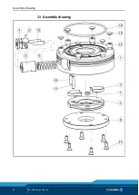
Page 21: ...ce the load The clamping area unlocks automatically Possible cause Corrective action The actuating piston or movement mechanism is damaged Disassemble the module and replace damaged and worn parts with original SCHUNK spare parts see chapter 8 Part list Item Designation Quantity 1 Base body 1 2 Drive ring 1 3 Clamping bar 2 4 Drive piston 1 5 Actuation piston 1 6 Cover 1 7 Bearing shell 1 8 Compre...

Page 22: ...Assembly drawing 22 02 NSE M plus 138 en Assembly drawing 11 ...

Reviews: