background image

Imprint

2

08.00 | NSE3 138, NSE-T3 138 | VERO-S quick-change pallet system | en |
1152197 -NSE3 NSE-T3

Imprint

Copyright:

This manual is protected by copyright. The author is SCHUNK GmbH & Co. KG. All rights
reserved.

Technical changes:

We reserve the right to make alterations for the purpose of technical improvement.

Document number:

 1152197 -NSE3 NSE-T3

Version:

 08.00 | 27/07/2022 | en

Dear Customer,
thank you for trusting our products and our family-owned company, the leading
technology supplier of robots and production machines.
Our team is always available to answer any questions on this product and other solutions.
Ask us questions and challenge us. We will find a solution!
Best regards,
Your SCHUNK team

Customer Management
Tel. +49–7572-7614-1300
Fax +49-7572-7614-1039
customercentermengen@de.schunk.com

Please read the operating manual in full and keep it close to the product.

Summary of Contents for VERO-S NSE3 138

Page 1: ...Translation of Original Operating Manual VERO S quick change pallet system NSE3 138 NSE T3 138 Assembly and Operating Manual...

Page 2: ...NSE T3 Version 08 00 27 07 2022 en Dear Customer thank you for trusting our products and our family owned company the leading technology supplier of robots and production machines Our team is always a...

Page 3: ...12 2 Protection during commissioning and operation 13 2 12 3 Protection against dangerous movements 14 2 12 4 Notes on particular risks 14 3 Product description 17 3 1 Description of design and versi...

Page 4: ...clamping area does not unlock properly 54 8 5 Malfunctions when loading and unloading the change interface with fitted cone seal 55 8 6 The cone seal does not seal 55 8 7 The media transfer unit of th...

Page 5: ...e a basic understanding and may deviate from the actual version In addition to these instructions the documents listed under 1 1 2 6 are applicable 1 1 1 Presentation of Warning Labels To make risks c...

Page 6: ...K NSE3 138 NSE3 138 K NSE3 138 V1 NSE3 138 V1 K NSE3 138 V4 NSE3 138 V4 K NSE3 138 P NSE3 138 P K NSE T3 138 NSE T3 138 K NSE T3 138 V1 NSE T3 138 V1 K KVS 40 cone seal 1 2 Warranty The warranty peri...

Page 7: ...over plugs 5 fastening screws M8 1 fitting screw M8 NSE T3 138 NSE T3 138 K NSE T3 138 V1 NSE T3 138 V1 K NSE T3 138 V4 NSE T3 V4 K 2 O rings 9 x 1 5 6 cover plugs 6 fastening screws M8 1 cylindrical...

Page 8: ...not being used as intended if for example It is used as a pressing tool a toolholder a load handling device or as lifting equipment It is used for turning applications over 100 rpm without consulting...

Page 9: ...rface and recesses indented to the locating surfaces above the mounting locations are always clean Under all circumstances prevent any type of chips from entering the interface and prevent cooling emu...

Page 10: ...us activities related to the product Trained electrician Due to their technical training knowledge and experience trained electricians are able to work on electrical systems recognize and avoid possib...

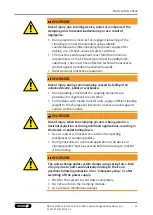
Page 11: ...irnet when dealing with moving components 2 8 Notes on safe operation Incorrect manner of working by personnel Working in an incorrect manner can make the product unsafe and risk the danger of serious...

Page 12: ...rectified Test the product after a malfunction to establish whether it still functions properly and no increased risks have arisen 2 11 Disposal Handling of disposal The incorrect handling of disposa...

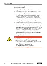
Page 13: ...serious injuries and even death Stand clear of suspended loads and do not step into their swiveling range Never move loads without supervision Do not leave suspended loads unattended 2 12 2 Protection...

Page 14: ...e defined by the movement range To avoid accidents and or material damage human access to the movement range of the machine must be restricted Limit prevent accidental access for people in this area d...

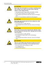
Page 15: ...in alignment to each other For modules with media transfer units apply sufficient loading weight to the changeover interface to ensure a level support surface on the module WARNING Risk of injury whe...

Page 16: ...injury due to compressed air hoses coming loose when connected improperly Use safety valves or safety switches Take appropriate protective measures to secure the danger zone CAUTION Risk of injury fro...

Page 17: ...transfer unit NSE3 99 x NSE3 99 K x NSE3 99 V1 x NSE3 99 V1 K x x NSE3 138 x NSE3 138 K x NSE3 138 V1 x NSE3 138 V1 K x x NSE3 138 V4 x NSE3 138 V4 K x x NSE3 138 P x NSE3 138 P K x x NSE T3 138 x NSE...

Page 18: ...N 75 kN 8 kN 28 kN NSE3 138 P K 1337167 35 kN 50 kN 75 kN 8 kN 28 kN NSE T3 138 1313726 35 kN 50 kN 75 kN 7 kN 24 kN NSE T3 138 K 1313727 35 kN 50 kN 75 kN 7 kN 24 kN NSE T3 138 V1 1313728 35 kN 50 kN...

Page 19: ...mission dB A 70 Pressure medium Compressed air compressed air quality according to ISO 8573 1 7 4 4 Protection class IP 67 The actuating pressure for the turbo function must not exceed 6 bar A separat...

Page 20: ...necessary to determine whether the machine mechanical equipment in which the quick change pallet system is to be installed corresponds to the provisions set out in the Machinery Directive If the quic...

Page 21: ...due to unexpected movements If the power supply is switched on or residual energy remains in the system components can move unexpectedly and cause serious injuries Before starting any work on the prod...

Page 22: ...itoring functions 4 3 Fastening and connection Flatness If several linked clamping modules are mounted make sure that the flatness and height deviation of the outer ring bearing surfaces from clamping...

Page 23: ...and ventilation via turbo connection hose free direct connection for turbo function Air bleeding and ventilation via the cover and open ventilation channel in the installation space Caution The set s...

Page 24: ...um pressure The matching NW3 coupling nipples must be installed in the opposite side to be connected The media transfer interfaces are actuated on the bottom of the module O rings are used to seal the...

Page 25: ...H6 The air connection usually occurs via the bottom coupling holes in the base of the unit Alternative connection option two M5 connections on the side In this case the bottom openings must be sealed...

Page 26: ...ut with a fitting screw with a diameter of 7 f7 x 3 mm Precise alignment and positioning of the quick change pallet system requires precise positioning of the fitting bore 7 H7 in the mounting positio...

Page 27: ...5 Slot for position orientation and torque transmission Fastening for the fitting screw All clamping systems of equal height within 0 02 mm Measure of clearance for fitting screw Measure of clearance...

Page 28: ...ernative connection option Two side G1 8 connections which are free when the lower centering diameter 110 H6 is used In this case the bottom openings must be sealed To do so insert the 9 x 1 5 O rings...

Page 29: ...ng position The air connection is normally made via the bottom coupling holes in the floor of the unit Hose free direct connection seal 9 x 1 5 Installation type full installation Detaching thread M10...

Page 30: ...l and full installation 138 H6 in the upper range The exact position orientation is done with a fitting screw with a diameter of 9 f7 x 5 mm Precise alignment and positioning of the quick change palle...

Page 31: ...artial installation Media transfer unit 2 Media transfer unit 1 Hose free direct connection seal 9 x 1 5 All clamping systems of equal height within 0 02 mm Detaching thread M10 x 10 M5 thread Mountin...

Page 32: ...the lower range For partial and full installation 138 H6 in the upper range The air connection is normally made via the bottom coupling holes in the collar of the housing of the unit Hose free direct...

Page 33: ...7 in the mounting position on the opposite side The air connection is normally made via the bottom coupling holes in the collar of the housing of the unit Hose free direct connection seal 9 x 1 5 Inst...

Page 34: ...including fitted sealing ring diagonally tilted into the change interface and tighten observing the tightening torque 4 7 46 4 Insert the compression springs 5 Insert the mounting diagonally into the...

Page 35: ...Assembly Sequence when inserting the cone seal 35 08 00 NSE3 138 NSE T3 138 VERO S quick change pallet system en 1152197 NSE3 NSE T3...

Page 36: ...heck the cone seal when loading with the clamping pallet The air connection for the blow out air air purge is achieved via the base M7 connection thread with the installation of a screw in union Alter...

Page 37: ...fficiently dimensioned threaded holes or a sufficiently thick mounting material The clamping pins can be attached to the workpiece or pallet in two different ways Preference should be given to the lef...

Page 38: ...38 K V1 V1 K V4 V4 K 68 mm Screw DIN EN ISO 4762 12 9 Customer specific pallet or device Screw DIN EN ISO 4762 12 9 Steel Aluminum Steel Aluminum Mounting the clamping pins Tolerances and installation...

Page 39: ...ring clearance of 0 1 mm Indexing pin for positional alignment and torque transmission with torque pin Positioning in one direction Positioning direction perpendicular to the positioning axis Select t...

Page 40: ...effects a build up of pressure in the OPEN condition The models NSE3 138 NSE3 138 K NSE3 138 V1 NSE3 138 V1 K NSE3 138 V4 NSE3 138 V4 K have two integrated pressure sensors With these the respective c...

Page 41: ...mic pressure monitoring of the OPEN clamping slide position for O ring 4 5 x 1 5 Clamping slide axis Air outlet for dynamic pressure monitoring of the clamping slide position OPEN Dynamic pressure NSE...

Page 42: ...AMPED Hose free direct connection for media transfer unit 2 Hose free direct connection for dynamic pressure monitoring of the CLAMPED clamping slide position Hose free direct connection for unlocking...

Page 43: ...ction 3 Slide monitoring for module OPEN 4 Slide monitoring for module CLAMPED 5 Media transfer unit 1 for the pneumatics and hydraulics as well as the vacuum can be connected when depressurized 6 Med...

Page 44: ...of the clamping pallet that is clamped and a differential pressure measurement can be carried out For NSE3 and NSE T3 by incorporating the connection thread in the center of the plug For NSE3 99 K NSE...

Page 45: ...be switched off before the pallet is placed on top otherwise a pressure cushion may form or vibrations may occur Recommendation Switch off blow off air before placing the pallet approx 1 mm Switch on...

Page 46: ...5 Tightening torques for the plug and cover conversion parts in the clamping pin mounting Component Plug basic version Bottom cover Tightening torque Nm 10 10 4 8 AFS 138 electronic monitoring system...

Page 47: ...th ventilation hole Accessories 1403711 4 For clamped modules without clamping pins actuate the dynamic pressure monitoring for face contact monitoring air purge Pressure in the set range 2 bar volume...

Page 48: ...Assembly 48 08 00 NSE3 138 NSE T3 138 VERO S quick change pallet system en 1152197 NSE3 NSE T3 Metallically dense ring contact surface Metallically dense ring contact surface...

Page 49: ...e actuated with the clamping module closed without clamping pins In this case the blow out air is discharged at the sealing position and in doing so blows coolant and chips from the bearing surface Wh...

Page 50: ...h two supply chambers can be controlled via the media transfer interfaces on the connected clamping pallet The pressure sealed coupling mechanisms do not open until coupling elements are connected Cou...

Page 51: ...y due to losing pallets or workpieces in the case of incorrect actuation caused by incorrect operation Risk of injury due to compressed air hoses coming loose when connected improperly Disconnect the...

Page 52: ...units is switched on or if residual energy is still present this can cause the clamping device to move unexpectedly during loading which may result in serious injuries Before starting any work on the...

Page 53: ...ing cover If the clamping module has to be disassembled send the module to SCHUNK for repair The back cover of the clamping module is spring preloaded and must only be removed by trained specialist pe...

Page 54: ...tenance unit with oiler Hose diameter below minimum Required hose diameters see chapter Securing and connecting 4 3 22 The turbo connection is still pressurized Ventilate the connection 8 3 The quick...

Page 55: ...ace Increase loading weight or pressure force 8 6 The cone seal does not seal Possible cause Remedial measures Sealing ring is damaged or deformed Remove seal and replace sealing ring Sealing ring is...

Page 56: ...E T3 138 NSE T3 138 K NSE T3 138 V1 NSE T3 138 V1 K NSE T3 138 V4 NSE T3 138 V4 K 1153524 KVS 40 cone seal 1153525 Contained items see 9 2 57 For wearing parts replacement is recommended when maintena...

Page 57: ...Cylindrical pin 2 x 21 Cylindrical screw 4 x 22 Set of compression springs 8 x 23 Locking screw 2 x 24 Countersunk screw 6 x 25 Set screw 2 x 26 Cylindrical screw 6 x 26 Cylindrical screw 5 x 27 Fitt...

Page 58: ...x x 11 O ring 1 x x 12 O ring 4 x x 13 O ring 1 x x 14 O ring 1 x x 15 Round cord section 3 2 x x 16 O ring 1 x x 17 O ring 1 x x 18 O ring 1 x x 19 O ring 4 x x 19 O ring 2 x x x 20 Slide bearing col...

Page 59: ...for NSE T3 138 and its versions f Only for version with media transfer unit NSE3 138 P NSE3 138 P K g included in the sealing kit h For version with V4 torque pin 9 2 3 Cone seal KVS 40 ID 1313742 It...

Page 60: ...00 NSE3 138 NSE T3 138 VERO S quick change pallet system en 1152197 NSE3 NSE T3 10 Assembly Drawings 10 1 Assembly NSE3 99 NSE3 99 K NSE3 99 V1 NSE3 99 V1 K NSE3 99 NSE3 99 V1 NSE3 99 K NSE3 99 V1 K...

Page 61: ...ly Drawings 10 2 Assembly NSE3 138 NSE3 138 K NSE3 138 V1 NSE3 138 V1 K NSE 138 V4 NSE3 138 V4 K NSE3 138 P NSE3 138 P K 61 08 00 NSE3 138 NSE T3 138 VERO S quick change pallet system en 1152197 NSE3...

Page 62: ...ssembly Drawings 62 08 00 NSE3 138 NSE T3 138 VERO S quick change pallet system en 1152197 NSE3 NSE T3 10 3 Assembly NSE T3 138 NSE T3 138 K NSE T3 138 V1 NSE T3 138 V1 K NSE T3 138 V4 NSE T3 138 V4 K...

Page 63: ...Assembly Drawings 10 4 KVS 40 cone seal 63 08 00 NSE3 138 NSE T3 138 VERO S quick change pallet system en 1152197 NSE3 NSE T3...

Page 64: ...336 1440337 1313721 1313722 1313723 1313724 1313726 1313727 1313728 1313729 1337166 1337167 The partly completed machine may not be put into operation until conformity of the machine into which the pa...

Page 65: ...l machine Fulfilled for the scope of the partly completed machine Not relevant 1 1 Essential Requirements 1 1 1 Definitions X 1 1 2 Principles of safety integration X 1 1 3 Materials and products X 1...

Page 66: ...ments X 1 4 2 Special requirements for guards X 1 4 2 1 Fixed guards X 1 4 2 2 Interlocking movable guards X 1 4 2 3 Adjustable guards restricting access X 1 4 3 Special requirements for protective de...

Page 67: ...ories of machinery X 2 1 Foodstuffs machinery and machinery for cosmetics or pharmaceutical products X 2 2 Portable hand held and or guided machinery X 2 2 1 Portable fixing and other impact machinery...

Page 68: ...Spanntechnik KG Lothringer Str 23 D 88512 Mengen Tel 49 7572 7614 0 Fax 49 7572 7614 1099 info de schunk com schunk com Folgen Sie uns I Follow us 07 2022 2022 SCHUNK GmbH Co KG 08 00 NSE3 138 NSE T3...

Reviews: