Assembly
40
08.00 | NSE3 138, NSE-T3 138 | VERO-S quick-change pallet system | en |
1152197 -NSE3 NSE-T3
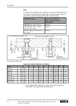
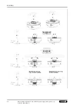
4.4.1 Information to clamping pin SPG 40
The SPG 40 can be used at a clamping area instead of the SPA 40.
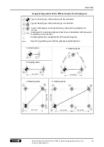
If there are several clamping areas, only the clamping area with
clamping bolt type SPA may be exchanged for the SPG 40.
The repeat accuracy increases to < 0.002 mm when using the SPG
40.
When connecting the screws from above, a 10 mm longer M12
screw of strength class 12.9 must be used according to the
mounting option on the left in the illustration.
4.5 NSE3 Dynamic pressure monitoring of the clamping slide
position
The models NSE3 99, NSE3 99-K, NSE3 99-V1, NSE3 99-V1-K have
integrated dynamic pressure monitoring. With these, the
respective clamping slide position effects a build up of pressure in
the "OPEN" condition.
The models NSE3 138, NSE3 138-K, NSE3 138-V1, NSE3 138-V1-K,
NSE3 138-V4, NSE3 138-V4-K have two integrated pressure
sensors. With these, the respective clamping slide position effects
a build up of pressure in the "OPEN" or in the "CLAMPED"
condition. Either just one of the two monitoring functions or both
simultaneously can be used for alternative control monitoring.
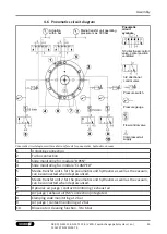
Actuating clamping slide monitoring requires a reduced pressure
supply that is limited to 2 bar (see chapter "Pneumatic circuit
diagram"
).
The measurable differential pressure must reach a minimum of 1
bar for assessment via the air gap sensor to be reliable. The
maximum pressure is 2 bar. Monitoring requires a pressure
gauge, an adjustable throttle and an air gap sensor.
For clamping slide monitoring, the designated connection must be
actuated via a floor-side drilled hole.
Request our installation drawings if performing the installation
yourself.

