Assembly
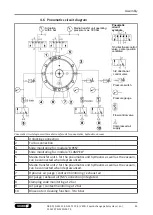
4.6 Pneumatics circuit diagram
Actuation
with 6 bar
Pneumatic
circuit
symbols
3/2 directional
control valve
Pressure switch
5/3 directional control
valve, center position
ventilated
Pressure gauge
Flow control valve
Compressed air
supply
Media transfer unit operating
pressure max. 300 bar
Pneumatic circuit diagram with media transfer unit for pneumatics, hydraulics, vacuum
1
Unlocking connection
2
Turbo connection
3
Slide monitoring for module "OPEN"
4
Slide monitoring for module "CLAMPED"
5
Media transfer unit 1 for the pneumatics and hydraulics as well as the vacuum,
can be connected when depressurized.
6
Media transfer unit 2 for the pneumatics and hydraulics as well as the vacuum,
can be connected when depressurized.
7
Optional: air purge / contact monitoring / exhaust air
*
Air purge / exhaust air (M7 connection) integrated
8
Clamping slide monitoring at 2 bar
9
Air purge / contact monitoring at 2 bar
10
Blow-out air cleaning function, 3 to 6 bar
43
08.00 | NSE3 138, NSE-T3 138 | VERO-S quick-change pallet system | en |
1152197 -NSE3 NSE-T3


