background image

Basic safety notes

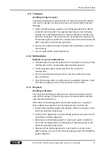
2.9 Transport

Handling during transport

Incorrect handling during transport can make the product unsafe
and risk the danger of serious injuries and considerable material
damage.
• When handling heavy weights, use lifting equipment to lift the

product and transport it by appropriate means. For clamping
station sizes 400 and above, the scope of delivery includes eye
bolts for transport. The eye bolts are intended for transporting
the clamping station without a workpiece and must be removed
after assembly of the clamping station.

• Secure the product during transport and handling to prevent it

from falling.

• Do not walk under suspended loads.

2.10 Malfunctions

Behavior in case of malfunctions

• Immediately remove the product from operation and report the

malfunction to the responsible departments/persons.

• Order appropriately trained personnel to rectify the

malfunction.

• Do not recommission the product until the malfunction has

been rectified.

• Test the product after a malfunction to establish whether it still

functions properly and no increased risks have arisen.

2.11 Disposal

Handling of disposal

The incorrect handling of disposal can make the product unsafe
and risk the danger of serious injuries and considerable material
and environmental harm.
After decommissioning, place the clamping device in a position
that enables any liquids in the clamping device to drain out.
• Collect the escaping liquids and dispose of them properly in line

with the statutory provisions.

• Follow local regulations on dispatching product components for

recycling or orderly disposal.

• Remove any identifiable plastic or aluminum parts installed in

or on the clamping device and dispose of them properly in line
with the statutory provisions.

• Dispose of the clamping device's metal parts as scrap metal.

Alternatively, you can return the clamping device to SCHUNK for
proper disposal.

11

03.00 | NSL3 | VERO-S quick-change pallet system | en | 1155408

Summary of Contents for VERO-S NSL3

Page 1: ...Translation of Original Operating Manual VERO S quick change pallet system NSL3 Assembly and Operating Manual...

Page 2: ...0 11 03 2022 en Dear Customer thank you for trusting our products and our family owned company the leading technology supplier of robots and production machines Our team is always available to answer...

Page 3: ...ental dangers 12 2 12 1 Protection during handling and assembly 12 2 12 2 Protection during commissioning and operation 12 2 12 3 Protection against dangerous movements 13 2 12 4 Notes on particular r...

Page 4: ...MDN 3 2 optional 40 6 Operation 41 7 Maintenance and care 42 7 1 Leak test 43 8 Troubleshooting 44 8 1 The clamping areas do not unlock 44 8 2 The clamping areas do not unlock perfectly 44 8 3 The qu...

Page 5: ...instructions the documents listed under 1 1 2 5 are applicable 1 1 1 Presentation of Warning Labels To make risks clear the following signal words and symbols are used for safety notes DANGER Danger...

Page 6: ...y date from factory or 500 000 cycles if it is used as intended under the following conditions Observe the applicable documents 1 1 2 5 Observe the ambient conditions and operating conditions 2 5 9 Ob...

Page 7: ...aling nipple G1 8 1 pneumatic plug in connection G1 8 8 6 for nominal hose width 6 2 eye bolts M8 NSL3 800 1 sealing ring G1 8 1 sealing nipple G1 8 1 pneumatic plug in connection G1 8 8 6 for nominal...

Page 8: ...is used for turning applications without consulting SCHUNK It is used in working environments that are not permissible People work on machines or technical equipment that do not comply with the EC Ma...

Page 9: ...te the unlocking process and allow the interface to dry out in an actuated state or carefully blow out with compressed air using suitable protective equipment Only use high quality cooling emulsions w...

Page 10: ...r the required personal protective equipment Observe the valid safety and accident prevention regulations Wear protective gloves to guard against sharp edges and corners or rough surfaces Wear heat re...

Page 11: ...y the malfunction Do not recommission the product until the malfunction has been rectified Test the product after a malfunction to establish whether it still functions properly and no increased risks...

Page 12: ...the product s safety and cause serious injuries and considerable material damage Have all work carried out by appropriately qualified personnel For all work secure the product against accidental oper...

Page 13: ...human access to the movement range of the machine must be restricted Limit prevent accidental access for people in this area due through technical safety measures The protective cover and protective...

Page 14: ...uipment WARNING Risk of injury when the clamping pin axis is being used in a horizontal position or during overhead applications resulting in the device or pallet falling down Use a crane or a transpo...

Page 15: ...oling lubricants or oil Ensure that the working environment is clean before starting assembly and installation work Wear suitable safety boots Follow the safety and accident prevention regulations whe...

Page 16: ...4762 12 9 Total pull down force total sum of pull down forces of all the clamping modules mounted in the clamping station Total pull in force with TURBO function for clamping station NSL3 V1 total sum...

Page 17: ...station and support area of the machine table must be clean and free of any contamination or damage WARNING Risk of injury due to unexpected movements If the power supply is switched on or residual e...

Page 18: ...zone must have sufficient rigidity in order to ensure the relative flatness of the clamping modules If several clamping stations are interlinked make sure that the flatness and height deviation of th...

Page 19: ...n the attached bore hole drawings Clamping stations from size NSL3 400 already have holes for at least two M10 mounting screws The mounting points are offset centrally between the clamping modules at...

Page 20: ...les when connecting and disconnecting the air supply at the clamping station When connecting the clamping station it must be taken into consideration that complete ventilation of the piston chambers i...

Page 21: ...ds on the number of quick change pallet modules installed inside one clamping station or in several clamping stations actuated with shared hose lines Then supply lines with the following minimum cross...

Page 22: ...educed material thickness in marked areas Bore holes permitted in shaded areas NSL3 150 V1 T 4 3 2 NSL3 200 The clamping station can be clamped directly onto the machine table via screws Permitted are...

Page 23: ...on the bottom of the clamping station to mount T nuts used for aligning the clamping station These allow for precise alignment along an alignment groove The NSL3 200 V1 T is equipped with two intercon...

Page 24: ...amped directly onto the machine table via screws Permitted areas for appropriate bore holes can be found in the attached bore hole drawings Optionally BRR 50 clamp banks can be purchased There are fou...

Page 25: ...ansverse to the operator side Size M10 screws can be used at the additional mounting points to achieve a more rigid set up when using clamps There are two alignment grooves on the bottom of the clampi...

Page 26: ...table via screws Permitted areas for appropriate bore holes can be found in the attached bore hole drawings Optionally BRR 50 clamp banks can be purchased There are already 4 mounting holes at a dist...

Page 27: ...via a pneumatic plug connection G1 8 8 6 or a sealing nipple accessory for locking couplings type NW 7 4 accessory The clamping station can be retrofitted at the connection points using a separately...

Page 28: ...when using clamps There are two alignment grooves on the bottom of the clamping station to mount T nuts used for aligning the clamping stations on the machine table These allow for precise alignment...

Page 29: ...Assembly Reduced material thickness in marked areas Bore holes permitted in shaded areas Reduced material thickness in marked areas NSL3 800 29 03 00 NSL3 VERO S quick change pallet system en 1155408...

Page 30: ...sufficiently dimensioned threaded holes or a sufficiently thick mounting material The clamping pins can be attached in two different ways to the workpiece or pallet the mounting variants are numbered...

Page 31: ...nder any circumstances Usage arrangement of the different types of clamping pins Application pallet with 6 clamping positions 0 015 for type C 0 015 for type B Type A clamping pin with positioning acc...

Page 32: ...class 12 9 must be used after order of preference 2 4 5 Clamping pallets PAL S PAL A optional There are suitable VERO S clamping pallets to be used as accessories for NSL3 clamping stations There are...

Page 33: ...8 170 262 Tightening torques for fastening the clamping station with BRR50 clamp blanks The clamp blanks that have been adjusted by the customer to correspond to the machine table must be fastened to...

Page 34: ...sing customer specific air connection plug in systems Use sealing nipples without shut off function with an open through hole to vent the clamping module piston chambers The corresponding valves sound...

Page 35: ...r is applied at the connection for the turbo function this function actively provides air pressure to support the spring actuated locking procedure of the quick change pallet module This increases the...

Page 36: ...ASL2 G1 8 To mount the connecting strip the front air connection sealing nipple is removed from the clamping station and in its place the connecting strip is directly adjusted via the hollow screw Th...

Page 37: ...the installation space Via the cone seal the quick change pallet system can be protected against the penetration of coolant and chips into the change interface Note The clamping stations VERO S NSL3...

Page 38: ...ystem can be mounted to the NSL3 clamping station upon customer request The monitoring system can evaluate whether the operating states is TENSIONED or UNLOCKED and transmit this data to the machine c...

Page 39: ...OCKED and transmit this data to the machine control system Workpiece contact monitoring is possible Note The technical data and the exact installation instructions for the AFS3 138 PMI can be found in...

Page 40: ...feed through allows for variable positioning on the base plate of the clamping station Attaching the media feed through requires additional screw threads on the clamping station Further details on the...

Page 41: ...Risk of injury due to losing pallets or workpieces in the case of incorrect actuation caused by incorrect operation Risk of injury due to compressed air hoses coming loose when connected improperly D...

Page 42: ...let system operates perfectly the following instructions are to be observed Pressure medium Compressed air compressed air quality according to ISO 8573 1 7 4 4 CAUTION A separate maintenance unit with...

Page 43: ...ing maintenance work 7 1 Leak test As part of a leak test the air and plug in connections and the coupling mechanism should be tested for leaks The following components are required for the leak test...

Page 44: ...ressure below minimum Check operating pressure min 5 bar The modules were not operated with oiled compressed air Install maintenance unit with oiler Hose diameter below minimum for required hose diame...

Page 45: ...1 2 Air duct strip 2 3 NSE3 138 2 5 O ring 2 6 O ring 4 7 Countersunk screw 4 8 Locking screw 1 12 Sealing ring G1 8 1 13 Sealing nipple G1 8 1 14 Pneumatic screw in union G1 8 6 4 1 21 Cylindrical c...

Page 46: ...Pneumatic screw in union G1 8 6 4 2 21 Cylindrical clamp blanks BRR 50 Optional NSL3 400 ID no 1323572 Item Designation Quantity 1 Base plate 1 2 Air duct strip 4 3 NSE3 138 4 5 O ring 4 6 O ring 8 7...

Page 47: ...3 800 ID no 1323575 Item Designation Quantity 1 Base plate 1 2 Air duct strip 8 3 NSE3 138 8 5 O ring 8 6 O ring 16 7 Countersunk screw 16 8 Locking screw 1 12 Sealing ring G1 8 1 13 Sealing nipple G1...

Page 48: ...ings 10 1 NSL3 with NSE3 138 V1 quick change pallet module Included with VERO S NSE3 138 V1 With VERO S NSE3 138 V1 Included with VERO S NSE3 138 V1 installed on delivery included in accessory pack al...

Page 49: ...ith VERO S NSE3 138 Included with VERO S NSE3 138 installed on delivery included in accessory pack alternative plug connection in accessory pack in NSL3 400 NSL3 600 NSL3 800 NSL3 49 03 00 NSL3 VERO S...

Page 50: ...ne may not be put into operation until conformity of the machine into which the partly completed machine is to be installed with the provisions of the Machinery Directive 2006 42 EC is confirmed Appli...

Page 51: ...sential Requirements 1 1 1 Definitions X 1 1 2 Principles of safety integration X 1 1 3 Materials and products X 1 1 4 Lighting X 1 1 5 Design of machinery to facilitate its handling X 1 1 6 Ergonomic...

Page 52: ...2 Interlocking movable guards X 1 4 2 3 Adjustable guards restricting access X 1 4 3 Special requirements for protective devices X 1 5 Risks due to other hazards 1 5 1 Electricity supply X 1 5 2 Stat...

Page 53: ...hinery X 2 1 Foodstuffs machinery and machinery for cosmetics or pharmaceutical products X 2 2 Portable hand held and or guided machinery X 2 2 1 Portable fixing and other impact machinery X 2 3 Machi...

Page 54: ......

Page 55: ......

Page 56: ...HUNK GmbH Co Spanntechnik KG Lothringer Str 23 D 88512 Mengen Tel 49 7572 7614 0 Fax 49 7572 7614 1099 info de schunk com schunk com Folgen Sie uns I Follow us 03 2022 2022 SCHUNK GmbH Co KG 03 00 NSL...

Reviews: