Adjustment Work
Single Arm Pantograph WBL 85 Balfour Beatty
Page 32
WBL 85-15kV
10.9
Adjustment of Contact Force Monitoring System
Instructions:
❑
Loosen securing screws (1) of 3/2-way valve
❑
Slide valve (5) down all the way
❑
Switch pantograph in raising position
❑
Apply load on contact strip (2) vertically, until lever (3) contacts the regulating
screw (4). (The pan must have been adjusted before – see 10.8.)
❑
Slide the valve (5) upwards over oblong holes until the lifter of valve (5) is
actuated by the pan spring, causing the signal of the compressed air horn to
cease.
❑
Tighten screws (1).
❑
Check: Tension and release contact strip. As soon as the lever (3) hits the
regulating screw (4), the acoustic signal must cease. Whenever
lever (3) moves away from screw (4), the signal horn must sound.
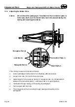
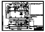
Securing Screw (1)
Valve (5)
Lever (3)
Contact Strip (2)
Regulating Screw (4)
Summary of Contents for WBL 85 Balfour Beatty
Page 34: ......
Page 35: ......
Page 36: ......
Page 37: ......
Page 38: ......
Page 39: ......
Page 40: ......
Page 41: ......
Page 42: ......
Page 43: ......
Page 44: ......
Page 45: ......
Page 46: ......
Page 47: ......
Page 48: ......
Page 49: ......
Page 50: ......
Page 51: ......
Page 52: ......
Page 53: ......
Page 54: ......
Page 56: ......

