background image

Appendix

Single Arm Pantograph WBL 85 Balfour Beatty

Page 55

WBL 85-15kV

12. Annex

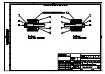
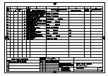
Pneumatic diagramm drawing no. 3-9919.4963

Summary of Contents for WBL 85 Balfour Beatty

Page 1: ...Pantograph Model WBL 85 Balfour Beatty Permaquip SRS Issue 1 00 Made available 25 05 00 Description no 4 991B 5111 Designed Techdok Zauner GmbH Checked approved Santner Description Maintenance and Operating Manual ...

Page 2: ...r Frame 9 4 2 3 Upper Frame 9 4 2 4 Coupling Rod 9 4 2 5 Pan Head 9 10 4 2 6 Parallel Guide Bar 10 4 2 7 Air Bellow Drive 10 4 2 8 Electrical Equipment 10 4 2 9 Pneumatic Control Unit 10 4 2 10 Compressed Air Chamber 11 4 2 11 Compresse Air Signal Horn 11 4 2 12 Ltach 11 5 Assembly 12 to 13 5 1 General Information 12 5 2 Transport 12 5 3 Mounting 12 5 4 Installation of Electrical Equipment 13 5 4 ...

Page 3: ...rs of component parts 21 to 23 9 4 1 Free Bearing of Base Frame and Upper Frame 21 9 4 2 Fixed Bearing of Base Frame Coupling Rod and Upper Frame 22 9 4 3 Pan Head 22 9 4 4 Bellow Drive 23 9 4 5 Other Component Parts 23 9 5 Re assembly after Complete Disassembly 23 24 10 Adjustment Work 24 to 30 10 1 General Information 24 10 2 Adjustment of Coupling Rod and Resting Position 25 10 3 Adjusting the ...

Page 4: ...perating safety The last chapter contains the spare parts drawings We kindly request you to describe the needed parts as accurate as possible and in accordance with this catalogue to assure a problem free order processing and subsequent delivery Page 4 WBL 85 15kV Copyright by Schunk Bahntechnik Ges mbH All rights reserved This publication may not be reproduced stored in a retrieval system or tran...

Page 5: ...r correct earthing If the overhead wire is voltage free raise the pantograph up to the catenary 2 2 1 Safety Device During raising and lowering of the pantograph a signal horn sounds As soon as the pantograph has reached the desired contact pressure for the appropriate earthing function the acoustic signal ceases If the contact pressure falls below the preset level then the signal sounds indicatin...

Page 6: ...air and maintenance work ensure that the power to the catenary is switched off the pantograph is lowered After competing any repair and maintenance work ensure that no tools or other loose parts have been left on the vehicle roof 2 2 4 Transport Attention Persons are not allowed to stay underneath the pantograph during lifting and transportation ...

Page 7: ... height and a lateral force of 300 N according to IEC 494 30 mm Weight 120 kg Contact strip length 920 mm Pan width 1600 10 mm Pan height 300 5 mm Contact strip width 35 mm Contact strip material Graphit carbon Rated voltage 25 kV Static contact force 120 N 10 N adjustable Rising time to max working height max 10 sec Lowering time from max working height max 10 sec Supply pressure from vehicle min...

Page 8: ... the Single Arm Pantograph WBL 85 are Low weight Simple construction Minimum maintenance Excellent contact behavior even under basic catenary conditions Maximum operating safety 4 2 Structural Components Bellow Drive Lower Frame Upper Frame Coupling Rod Pneumatic Control Unit Pan Head Parallel Guide Bar Latch Compressed Air Chamber Base Frame Signal Horn ...

Page 9: ...pes Parallel guide bar 4 2 3 Upper Frame The upper frame is a welded structure made of seamless tubes Necessary lateral stability is achieved through a cross wire rope construction Attached to the upper frame are the following component parts Pan head Coupling rod Lower frame Bearing blocks for the knuckle joint bearings 4 2 4 Coupling Rod The coupling rod consists of two individually welded round...

Page 10: ...6 Parallel Guide Bar The parallel guide bar prevents the pan head from rotating It holds the collector strip in a horizontal position 4 2 7 Air Bellow Drive The pneumatic bellow drive allows the pantograph to rise It is mounted between the base frame and the lower frame A pneumatic line connects the bellow drive with the valve control unit The contact pressure as well as the raising and lowering t...

Page 11: ...able to enable the signal horn to sound for the appropriate duration 4 2 12 Compressed Air Signal Horn A signal horn is attached to the baseframe The horn sounds during the raising and lowering operations and when there is too little contact pressure onto the catenary As soon as the pantograph has reached the required contact pressure for correct earthing function the acoustic signal ends A monito...

Page 12: ...tion and lifting purposes fix panto only on fixing points 1 2 3 4 of the base frame Attention No one admitted underneath the pantograph during lifting and transportation Caution Do not damage coating during transportation 5 3 Mounting The base frame has to be mounted tension free onto the vehicle roof The base pipe of the lower frame has to be horizontal If needed washers may be installed undernea...

Page 13: ... greased with conducting grease WBL 85 15kV Assembly Single Arm Pantograph WBL 85 Balfour Beatty Page 13 5 5 Mounting of Pneumatic Air Connection The pneumatic connection between vehicle and pantograph has to be accomplished on the connections 1 and 2 Both connection have a 1 4 inside thread Connection 1 Connection for pantograph airbellowdrive Connection 2 Connection for latch 2 1 1 ...

Page 14: ...1 Checklist also see 10 Adjustment Check before start up Screw connections of high voltage hook up and verify that they are well greased Contact pressure of pantograph 120N 10N Raising and Lowering time to be in according with technical data Check signal horn for proper function see 2 2 ...

Page 15: ...ion upward force adjust if necessary Inspection easy motion of bearings pan head springs etc Pneumatic equipment for leakages After max 3 years Grease the ends of the tow rope with TOP 2000 of AGIP Schmiertechnik Replace shunts After every 8 to 10 years and on any main inspection max after 2000000 km 1250000 miles Change all ball bearing Inspect for corrosion if necessary replace coaling Change ru...

Page 16: ...completely with grease TOP 2000 of AGIP Schmiertechnik in order to avoid condensation 7 3 2 Plain Bearing All plain bearings of pantograph WBL 85 are maintenance free The plain bearings are either Teflon coated bronze bushings or Plastic bushings If plain bearings are slow reason of slowness has to be determined and eliminated Damaged plain bearings need to be exchanged Dirty plain bearings have t...

Page 17: ...ellow drive for operation during each main inspection by lifting and lowering the pantograph If needed replace damaged or bent parts The cables are to be greased with TOP 2000 of AGIP Schmiertechnik if necessary 7 6 Pneumatic Control Unit During each main inspection the safety valve needs to be tested by increasing the pressure through the pressure regulator After completed test adjust contact pre...

Page 18: ...10 7 adjust turning capacity of pantograph head Replace cables adjust bellow to achieve straight expanding line also see 10 3 adjusting the bellow drive Replace cables and grease in area of cam disk with non water soluble grease Tighten screws Exchange leaking hose with new hose line Air bellow damaged Cable torn Pneumatic control unit defective Pneumatic tube defect Inner friction of panto is too...

Page 19: ...sure regulator 0 5 l min Pressure regulator defective Monitoring valve on pan defective Restrictor in compressed air line defective Compressed air line defective Signal horn defective Contact force incorrectly set Monitoring valve on pan poorly set Pan head spring stop incorrectly set Excessive inner friction of pantograph Pan lever bearings are stiff Excessive air leakage Increase of contact pres...

Page 20: ... at the transport fixing points see 5 2 Transport Chapter Detach pantograph from fixing supports on vehicle Lift pantograph off vehicle roof Attention No persons is allowed to be underneath the transported pantograph 9 3 Complete Disassembly of Pantograph Mount pantograph on suitable resting feets to protect air bellow and signal horn Lower pantograph into lowest resting position Detouch signal ho...

Page 21: ...th retaining rings 4 with retaining ring pliers Push bearing shaft 2 out of grooved ball bearing 3 clean check for movebility and bearing play and replace if necessary Assembly of bearings vice versa pack space between grooved ball bearings with grease TOP 2000 of AGIP Schmiertechnik Cover Plate 1 Grease TOP 2000 of AGIP Schmiertechnik Bearing Housing 5 Retaining Ring 4 Grooved Ball Bearing 3 Bear...

Page 22: ...rsa pack space between grooved ball bearings with grease TOP 2000 of AGIP Schmiertechnik 9 4 3 Pan Head Detach 3 2 way monitoring valve from pantube Detach pneumatic screw joints and blind from 3 2 way valve Detach collectorstripsupport from levers Detach axle and springroll from collectorstripsupport Detach levers from pantube Detach leafsprings and underlayingsprings from pantube Detach axles an...

Page 23: ... 5 Other Component Parts If the pantograph is damaged all components need to be checked very carefully and replaced if needed 9 5 Re assembly after Complete Disassembly If the pantograph had been completely disassembled the re assembly is to be conducted as follows Mount free bearings and fixed bearings for lower frame as well as rubber puffer Attach cam discs to lower frame Mount lower frame to b...

Page 24: ...lve Screw 3 2 way monitoring valve to pantube Mount horns and tubs to collectorstrip Mount collectorstrip complete with horns on collectorstripsupport Attach bearing for parallelguide to pantube Mount panhead on upperframe Assemble parallel guide bar Attach parallel guide bar between lower frame and pan head mount Mount latch on base frame Mount shunts Screw pneumatic control unit to baseframe Scr...

Page 25: ...er Adjust coupling rod and resting position Adjust contact pressure Adjust curve of contact pressure Adjust turning of pan head Adjustment of pan Adjustment of contact force monitoring system 10 2 Adjustment of Coupling Rod and Resting Position The resting position of the pantograph is adjusted through the coupling rod 1 Instructions Adjustments are made through the rod adjuster 6 on the coupling ...

Page 26: ...etween the connection plate 1 and base shaft 2 is accomplished Verification through raising and lowering of pantograph Secure again with lock nuts Final inspection of the fine tuning through raising and lowering of the pantograph 10 3 Adjusting the Bellow Drive Check Lift and lower the pantograph Parallelism of the connection plate 1 to the base shaft 2 of the lower frame has to be assured during ...

Page 27: ...t pressure from resting position with slow ascending motion into the highest working position Results Value 1 Value 2 2 Friction Difference of contract pressure between Value 1 and Value 2 ideal value lower than 20 N If the difference of the contact pressure is greater than 40 N determine the reason e g defective component part dirt in the bearings etc and have it corrected Average Value Contact P...

Page 28: ...an be made by turning the regulation screw 2 of the throttle valve 1 Throttle Valve 1 Regulation Screw 2 Adjustment For increasing the raising and lowering time turn regulation screw 2 into clockwise direction For decreasing the raising and lowering time turn regulation screw 2 against clockwise direction The max raising and lowering time up to max working height is 10 sec ...

Page 29: ...wer frame Adjustment through Turns clockwise contact pressure increases in the lower working range Turns counter clockwise contact pressure decreases in the lower working range Adjustment is required until curve of contact pressure is nearly constant over the entire working range Verification with spring balance or with the SCHUNK pantograph contact pressure measuring gauge KM 11 Then tighten lock...

Page 30: ... rod end 1 After adjustment tighten lock nut and re check adjustment 10 7 Adjust Turning of Pan Head The adjustment of the panheadturning has to be made in medium workingheight of the pantograph about 1100 mm above resting position By means of the adjustment on the parallelguide the contact strip surface A has to be adjusted to an exact horizontal position Measurement can by made by means of a spi...

Page 31: ...lance onto contact strip 3 and pull down vertically with 90 N Screw out regulating screw 2 until screw sits against lever 4 Tighten lock nut 1 Allow pan to release Check Pull down contact strip vertically again by means of spring balance and check whether vertical movement of contact is blocked by screw 2 exactly at a force of 90 N Lock Nut 1 Regulating Screw 2 Contact Strip 3 Lever 4 ...

Page 32: ...contacts the regulating screw 4 The pan must have been adjusted before see 10 8 Slide the valve 5 upwards over oblong holes until the lifter of valve 5 is actuated by the pan spring causing the signal of the compressed air horn to cease Tighten screws 1 Check Tension and release contact strip As soon as the lever 3 hits the regulating screw 4 the acoustic signal must cease Whenever lever 3 moves a...

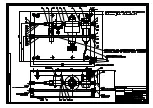
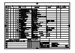
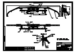
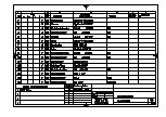
Page 33: ... of pantograph Drawing number item number on drawing name and number of component part Required quantity The component parts are shown on the following drawings annexed hereto 1 9910 4961 Pantograph WBL 85 1 B14 2022 Bellow drive 1 9915 4985 Pneumatic control 1 9918 4957 Pan Head 1 KL19 2700 Latch 3 L03 1977 Upper frame bearing 3 L01 1973 Base frame bearing ...

Page 34: ......

Page 35: ......

Page 36: ......

Page 37: ......

Page 38: ......

Page 39: ......

Page 40: ......

Page 41: ......

Page 42: ......

Page 43: ......

Page 44: ......

Page 45: ......

Page 46: ......

Page 47: ......

Page 48: ......

Page 49: ......

Page 50: ......

Page 51: ......

Page 52: ......

Page 53: ......

Page 54: ......

Page 55: ...Appendix Single Arm Pantograph WBL 85 Balfour Beatty Page 55 WBL 85 15kV 12 Annex Pneumatic diagramm drawing no 3 9919 4963 ...

Page 56: ......

Reviews: