

2. Assembly Instruction
Disconnect power before wiring.
Keep removed piece parts at a safe place to have them ready for reassembling.
1. Loosen cover screw and remove cover.
2. Loosen cable clamp screws and remove cable guard.
3. Insert cord into PVC-cable guard.
4. Remove outer jacket on cord ca. 25
mm
. Make sure not to hurt insulation of single conductors.
5. Strip bare each copper conductor 7
mm
and crimp on multicore cable ends. Do not strip more than 7
mm
.
6. Loosen terminal screws but do not remove screws.
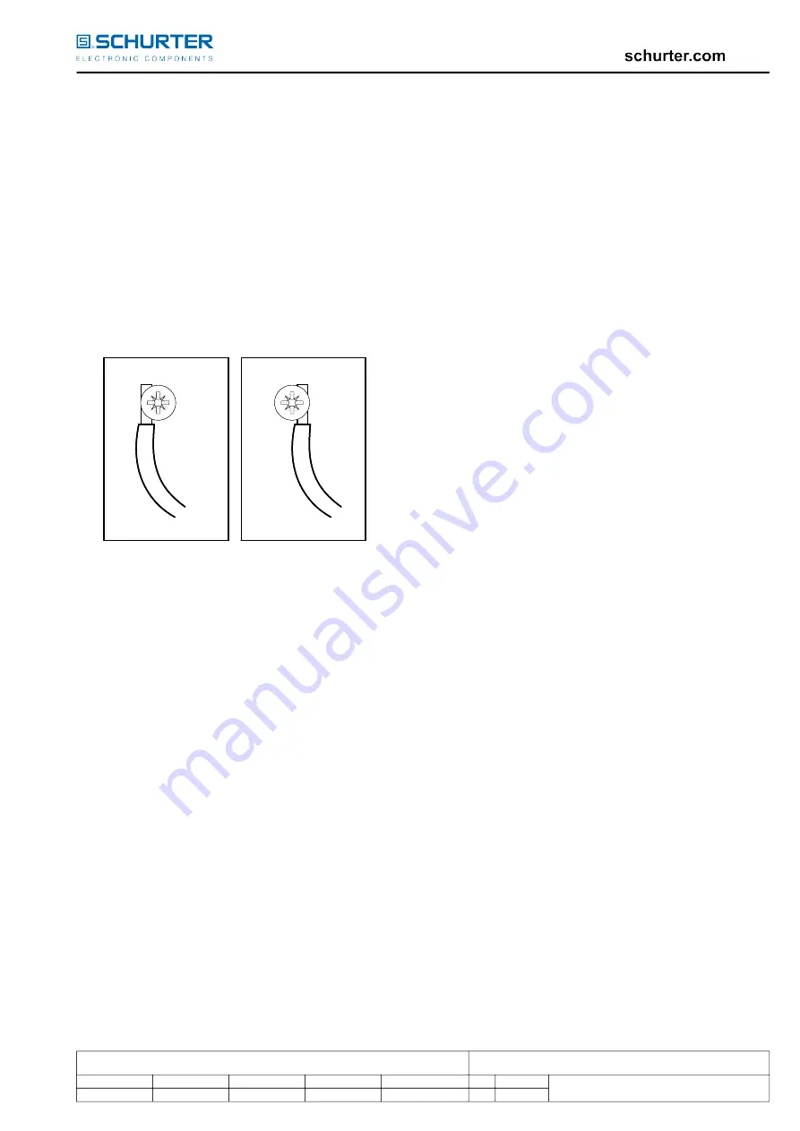
For connecting wires to terminals insert bare ends of conductors from left side of terminal screw according to figure
below. Make sure that no copper strands splice off when connecting conductors to clamps.
correct
wrong
P
O
7. Connect green or green/yellow (ground) wire to center clamp marked with ground symbol.
8. Connect blue (white or light grey)
wire to clamp marked „N“ (neutral).
9. Connect brown (black
/ “hot”) wire to clamp marked „L“ (line).
10. Tighten all wire clamp screws with a torque of 0,8
Nm
.
11. Insert shoulder of PVC-cable guard into cutout of base unit.
12. Assemble cable clamp over cut-off end of outer jacket of the cord and tighten cable clamp screws with a
torque of 0,4
Nm
.
13. Assemble cover unit and tighten cover screw with a torque of 0, 4
Nm
.
Warning: Failure to wire as instructed may cause personal injury or damage to device or equipment.
To be installed or checked by an qualified person only.
For factory assembly only.
2. Assembly Instruction
Disconnect power before wiring.
Keep removed piece parts at a safe place to have them ready for reassembling.
1. Loosen cover screw and remove cover.
2. Loosen cable clamp screws and remove cable guard.
3. Insert cord into PVC-cable guard.
4. Remove outer jacket on cord ca. 25
mm
. Make sure not to hurt insulation of single conductors.
5. Strip bare each copper conductor 7
mm
and crimp on multicore cable ends. Do not strip more than 7
mm
.
6. Loosen terminal screws but do not remove screws.
For connecting wires to terminals insert bare ends of conductors from left side of terminal screw according to figure
below. Make sure that no copper strands splice off when connecting conductors to clamps.
correct
wrong
P
O
7. Connect green or green/yellow (ground) wire to center clamp marked with ground symbol.
8. Connect blue (white or light grey)
wire to clamp marked „N“ (neutral).
9. Connect brown (black
/ “hot”) wire to clamp marked „L“ (line).
10. Tighten all wire clamp screws with a torque of 0,8
Nm
.
11. Insert shoulder of PVC-cable guard into cutout of base unit.
12. Assemble cable clamp over cut-off end of outer jacket of the cord and tighten cable clamp screws with a
torque of 0,4
Nm
.
13. Assemble cover unit and tighten cover screw with a torque of 0, 4
Nm
.
Warning: Failure to wire as instructed may cause personal injury or damage to device or equipment.
To be installed or checked by an qualified person only.
For factory assembly only.
owner
vettersa
creation date
22.10.2019
release date
22.10.2019
released by
vettersa
change order no
2018605
rev
G
page
2 of 2
0115.0049
Operation Manual
Wiring for 4796


