11
11
Technical Features
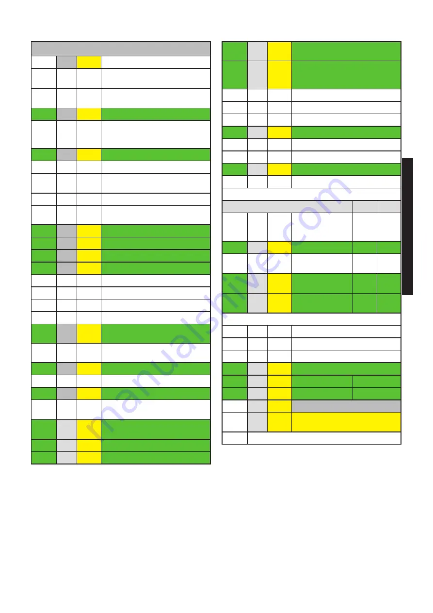
KEY
N°
C.E. S.E.
Description
1
db
SS
Domestic hot water temperature
sensor
(N.U.)
2
FLS
Flow switch with cold water filter
(N.U.) Optional
3
VG
Gas valve
4
Fd
E.
ACC
/RIL
Ignition/detection electrode
(N.U.)
5
Burner
6
Combustion chamber
(N.U.)
7
AF
TF
Flue gas anti-overflow thermostat
(N.U.)
8
Expansion vessel
(N.U.)
9
FR
HT
Heat exchanger
(N.U.)
10
HL
TL
Safety thermostat
11
Hb
SR
Heating temperature sensor
12
Ht
P
Pump (optional on BWA 50)
13
Lp
DK
Water deficiency pressure switch
14
Boiler drain valve
(N.U.)
15
Filling valve
(N.U.)
16
Diverting Valve (N.U.)
17
Plate heat exchanger
(N.U.)
18
FL
FH
VM
Fan
19
AF
AS
PV
Flue gas pressure switch
(N.U)
20
Safety valve
21
Automatic by-pass
(N.U.)
22
rb
SRR
Return temperature sensor
23
tf
TLC
Flue gas collector safety thermo-
stat
(N.U.)
24
Aluminium Heat Exchanger/
Capacitor
25
Vent valve
26
Condensation drain trap
27
E.
RIL.
Detection electrode
28
E.
ACC.
Ignition electrode
29
Return shut-off valve (N.U.)
30
SMG Sensor Flow General (N.U.)
31
Condensation drain trap
(N.U.)
32
Outlet flue inspection
33
Heatthing Controller HSCP (N.U.)
34
Gas cocks (N.U.)
35
Ignition Trasformer
36
Non return valve (N.U.)
BwA
50
70
C
Domestic hot
water outlet
(only with ACS kit)
G
Ingresso gas
G ¾’’
G ¾’’
F
Cold water inlet
(only with ACS kit)
M
Heating system
flow
G 1’’
G1 ¼’’
R
Heating system
return
G 1’’
G1 ¼’’
Rc
Filling valve
(N.U.)
Sc
Boiler drain
(N.U.)
Svs
Safety valve drain
(N.U.)
S
cond
Condensation drain
A
Air Suction
Ø 80
S
Exhaust Smoke
Ø 80
C.E.
=
ERROR CODES see par. 4.6
S.E.
=
WIRING DIAGRAM
KEY see par. 4.5
(N.U)
Component not used
Summary of Contents for BWA R50
Page 1: ...INSTALLATION AND SERVICING MANUAL R 50 R 70 BWA R 50 R 70 ...
Page 2: ...2 ...
Page 20: ...20 DOUBLE Ø 80 ...
Page 39: ......


