background image

13

13

Technical Features


BWA R 50 c

BWA R 70

Appliance category


II

2H3P

II

2H3P

Modulation Ratio 


 1:5

1:7

Nominal Heat Input on P.C.I. Qn

kW

48,5

67,5

Minimum Heat Input on P.C.I. Qmin

kW

9,6

9,6

Nominal Output (Tr 60 / Tm 80 °C) Pn

kW

47,2

65,5

Minimum Output (Tr 60 / Tm 80 °C) Pn min 

kW

9,1

9,1

Nominal Output (Tr 30 / Tm 50 °C) Pcond 

kW

49,3

68,5

Minimum Output (Tr 30 / Tm 50 °C) Pcond min

kW

10,3

10,3

Efficiency at max. output (Tr 60 / Tm 80°C)

%

97,29

 97,29

Efficiency at min. output (Tr 60 / Tm 80°C) 

%

94,9

 94,9

Efficiency at max. output (Tr 30 / Tm 50°C))

%

101,62

101,51

Efficiency at min. output (Tr 30 / Tm 50°C)  

%

104,3

104,3

Rendimento al 30% del carico (Tr 30°C)

%

107,33

107,33

Number of stars (according to 92/42 EEC)


Combustion  efficiency with nominal load 

%

97,80

97,41

Combustion efficiency with minimum load

%

98,42

98,42

Heat loss at casing with burner in operation (Qmin)

%

3,61

3,61

Heat loss at casing with burner in operation (Qn)

%

0,51

0,12

Stand-by losses (with ∆t 30°C)

%

0,2

0,2

Flue gas temperature tf-ta  (min)(**) 

°C

33

33

Flue gas temperature tf-ta  (max)(**)

°C 

43,6

51,3

Flue gas mass flow rate (min)

kg/h

15,9

15,9

Flue gas mass flow rate (max)

kg/h

80,0

111,4

Excess λ air

%

26,84

20,57

(***) CO

(min/max)

%

9,0- 9,2

9,5 - 9,5

Flue losses with burner in operation (min)

%

1,58

1,58

Flue losses with burner in operation (max)

%

2,20

2,59

Flue losses with burner off (depression “0”)

%

0,2

0,2

Portata d’acqua  alla potenza nominale (∆T 15°C)

l/h

2837

3927

Portata d’acqua  alla potenza nominale (∆T 20°C)

l/h

2120

2946

Minimum heating circuit pressure

bar

0,5

0,5

Maximum heating circuit pressure

bar

6

6

Max allowable pressure of the generator

bar

8

8

Water content

l

3,9

3,9

Gas Consumption Natural (20 mbar) gas G 20 a Qn

m

3

/h

5,13

7,14

Gas Consumption Natural gas (20 mbar) G 20 a Qmin

m

3

/h

1,02

1,02

Gas Consumption G25 (supply pressure 25 mbar) Qn

m

3

/h


Gas Consumption G25 (supply pressure 25 mbar) Qmin

m

3

/h


Gas Consumption G31 (supply pressure 37/50 mbar)

 Qn

kg/h

3,76

5,24

Gas Consumption G31 (supply pressure 37/50 mbar)

 Qmin

kg/h

0,75

0,75

Max. available pressure at the chimney base

Pa

40

40

Condensate production max

kg/h

7,8

10,87

Emissioni

CO at Minimum Heat Input with 0% of O2

mg/kWh

19,7

19,7

NOx at Nominal Heat Input with 0% of O2

mg/kWh

68

68

NOx at Minimum Heat Input with 0% of O2

mg/kWh

37

37


NOx Weighted value according EN 15420)

mg/kWh

33,9

34,68

NOx Class

5

5


Electrical Data

Voltage/Frequency electric power supply

V/Hz

230/50

230/50

Fuse on main supply

A (R)

4

4

Maximum absorbed output 

W

172

290

Minimum absorbed output 

W

77

145

Standby Consumption

W

16

16

Insulation degree

IP

X4D

X4D

(*)       (*) Room Temperature = 20°C
(**)     Temperatures detected with the unit in operation 

(Tr 60 / Tm 80°C)

(***)    See table INJECTORS PRESSURES





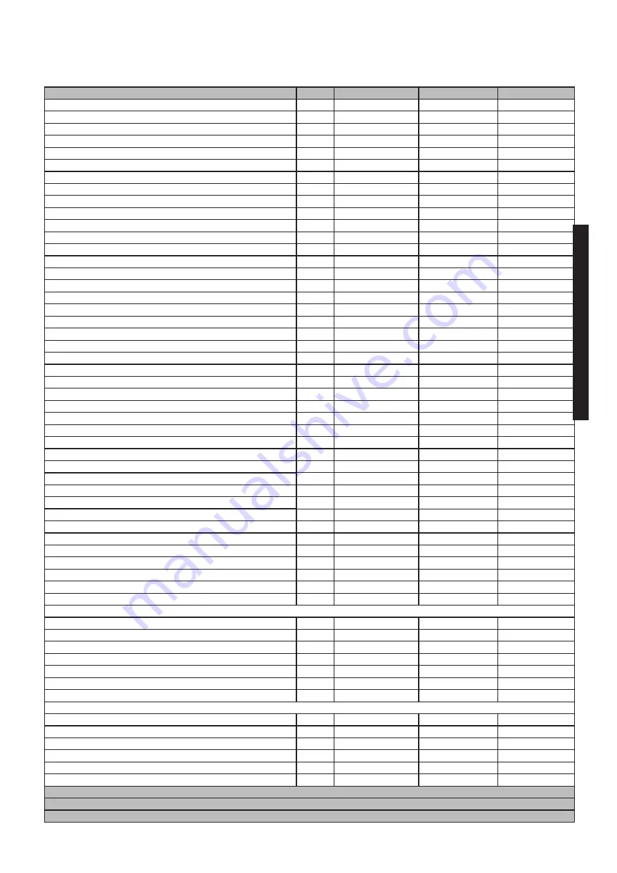
2.5 - OPERATING DATA ACCORDING TO UNI 10348  and GENERAL FEATUREs

For the adjustment data: NOZZLES - PRESSURE - DIAGRAMS - FLOW RATES - CONSUMPTION refer to the paragraph ADAP

-

TATION TO OTHER TYPES OF GAS.

Summary of Contents for BWA R50

Page 1: ...INSTALLATION AND SERVICING MANUAL R 50 R 70 BWA R 50 R 70 ...

Page 2: ...2 ...

Page 3: ... 26 3 12 Burner adjustment 27 3 12 1 Adaptation of the power to the heating system 29 Attention this manual contains instructions for the exclusive use of the professionally qualified installer and or maintenance technician in compliance with current legislation The user is NOT qualified to intervene on the boiler The manufacturer will not be held liable in case of damage to persons animals or obj...

Page 4: ...nd must be kept by the user Read the warnings contained in this instruction booklet carefully as they provide important guidelines regarding installation use and maintenance safety Keep the booklet with care for further consultation Installation and maintenance must be performed in compliance with the standards in force according to the instructions of the manufacturer up to standard and by person...

Page 5: ...keep this documentation safe for future consultation Inform the user about the importance of the air vents and the flue gas exhaust system highlighting their essential features and the absolute prohibition of modifying them Inform the user concerning controlling the system s water pressure as well as operations to restore it Inform the user concerning correct temperature control control units ther...

Page 6: ...he operating safety of the appliance Attention To tighten or loosen the screwed fittings use only appropriate fixed spanners Incompliant use and or inappropriate tools can cause damage e g water or gas leakage ATTENTION Indications for propane gas fired appliances Make sure that the gas tank has been deaerated before installing the appliance For state of the art tank venting contact the LPG suppli...

Page 7: ...utput 10 Pcond Effective output in condensation 11 Qmax Maximum heat output 12 Adjusted Qn Adjusted for rated heat output 13 PMS Max heating operating pressure 14 T max Max heating temperature B Domestic hot water circuit characteristics 15 Qnw Rated heat output in domestic hot water function if different to Qn 16 D Specific D H W flow rate according to EN 625 EN 13203 1 17 R factor No of taps acc...

Page 8: ...iler caused by the formation of fouling or by cor rosive water will not be covered by the warranty VALUE MIN MAX PH 6 5 8 Hardness fr 9 15 This protection can intervene only if the electricity and gas supplies are connected If one of the two is not available and upon reset 11 SR a temperature between 2 5 C is detected the appliance will behave as described in tab pos 2 The heating system can be pr...

Page 9: ...9 9 Technical Features BWA R 50 BWA R 70 2 2 2 VIEW WITH THE INDICATION OF THE MAIN COMPONENTS TECHNICAL FEATURES AND DIMENSIONS 2 1 TECHNICAL FEATURES ...

Page 10: ...10 The parts shown in gray are relative to the ACS kit 2 3 DIMENSIONS Front view View from below View from above Side view ...

Page 11: ...e 21 Automatic by pass N U 22 rb SRR Return temperature sensor 23 tf TLC Flue gas collector safety thermo stat N U 24 Aluminium Heat Exchanger Capacitor 25 Vent valve 26 Condensation drain trap 27 E RIL Detection electrode 28 E ACC Ignition electrode 29 Return shut off valve N U 30 SMG Sensor Flow General N U 31 Condensation drain trap N U 32 Outlet flue inspection 33 Heatthing Controller HSCP N U...

Page 12: ...he flow the pump in function of the Dt of the primary circuit BWA R 50 BWA R 70 Power supply in kW 49 3 68 5 Max flow rate demanded l h Dt 15 K 2826 3927 Nominal flow rate request Dt 20 K 2120 2946 residual pressure head BWA R 70 1 BWA R 50 2 1 PRESSURE LOSSES BWA R 50 Q water flow rate l h Pressure losses m H 2 O 2 4 DIAGRAM OF FLOW RATE PRESSURE AVAILABLE FOR INSTALLATION NOTE The use of a mixin...

Page 13: ...2 Portata d acqua alla potenza nominale T 15 C l h 2837 3927 Portata d acqua alla potenza nominale T 20 C l h 2120 2946 Minimum heating circuit pressure bar 0 5 0 5 Maximum heating circuit pressure bar 6 6 Max allowable pressure of the generator bar 8 8 Water content l 3 9 3 9 Gas Consumption Natural 20 mbar gas G 20 a Qn m3 h 5 13 7 14 Gas Consumption Natural gas 20 mbar G 20 a Qmin m3 h 1 02 1 0...

Page 14: ...nless the flue has been implemented to accommodate several utilities according to specific standards and regulations in force Only after this check can the fitting between the boiler and chimney flue be mounted Attention If there is dust and or if there are aggressive corrosive vapours present in the installation room the appliance must be protected suitably and must be able to operate independent...

Page 15: ...L width mm H heigh mm Net Weight kg Gross Weight kg 370 715 1025 50 55 BWA R 70 P depth L width mm H heigh mm Net Weight kg Gross Weight kg 370 715 1025 58 4 64 3 4 PACKAGING The boiler BWA 50 70 c is supplied completely assembled in a sturdy cardboard box After having removed the appliance from the packaging make sure that the supply is complete and undamaged The packaging elements cardboard box ...

Page 16: ...of combustion of condensing boilers and everything else applicable When choosing the place of the installation of the appliance follow the safety instructions below Place the appliance in rooms protected from frost Avoid installation in rooms with a corrosive or very dusty atmosphere The appliance must only be installed on a vertical and solid wall which can support its weight The wall must not be...

Page 17: ...500 Horizontal exhaust and intake terminals directed outside via coaxial or double pipes C33x C33 TOTAL LENGTH LA intake L Exhaust COAXIAL Ø60 100 DOUBLE Ø80 FROM m UP TO m FROM m UP TO m 1 7 0 5 0 5 40 20A 20S COAXIAL Ø80 125 DOUBLE Ø80 FROM m UP TO m FROM m UP TO m 1 9 1 1 20 10A 10S Vertical exhaust and intake terminals directed outside via coaxial or double pipes C53x C53 C53 NOT ALLOWED C53 T...

Page 18: ...ed for connection to a combustion air intake and combustion products evacuation system approved and sold separately ATTENTION The flue must comply with standards in force CAUTION LT total length is a reference value for the dimensioning of the ducts of A intake and S Exhaust Subtracting the values of LT reported at values of bends terminals extensions you get the value if 0 OK POSSIBLE configurati...

Page 19: ...to only use original Schuster exhaust pipes The supplier will have no contractual or ex tra contractual liability for damage caused due to incorrect installation and use and in any case failure to comply with the instructions provided by the manufacturer Adapter for double systems 80 125 2 3 COAXIAL DUCT Ø 80 125 ...

Page 20: ...20 DOUBLE Ø 80 ...

Page 21: ...o must respect and apply that foreseen by relevant laws in force in the local prescriptions of the supply company Incorrect in stallation can cause damage to persons animals and objects for which the manufacturer cannot be held responsible If you smell gas a Do not operate electric switches the telephone or any other object that may cause sparks b Immediately open doors and windows to create air c...

Page 22: ...e mains supply must be between 0 5 and 6 bar In case of higher pressure a pressure reducer it must be installed Attention Do not mix the heating water with incorrect concentrations of antifreeze or anti corrosion substances This could damage the gaskets and cause noise during operation Schuster will not be held liable for damage to persons animals or objects due to failure to comply with the above...

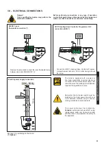
Page 23: ...nnect the HSCP Heating Slave Controller Program merwire between terminals BUS after having removed the jumper HSCP Heating Slave Controller Programmer E8 connection eBUS The boiler is equipped with a power ca ble boiler installation requires electric al connection to the mainspower supply This connection must be made up to standard as required the regulations in force Remember that a bipolar switc...

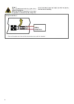
Page 24: ...als as indicated Safety Conection Danger Only a qualified technician may perform the electrical installation Before performing connections or any type of operation on electrical parts always dis connect electrical power and make sure that it cannot be reconnected accidentally ...

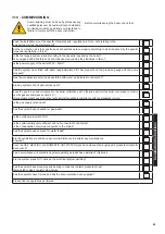
Page 25: ...in chapter 3 7 are any system shut off gate valves open does the gas to be used correspond to the boiler calibration gas otherwise perform the boiler conversion in order to use the gas available see section 4 3 this operation must be carried out by technical staff qualified in compliance with the standards in force is the gas supply valve open has the system been checked for gas leaks is the outsi...

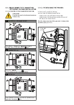
Page 26: ...PLUS and MINUS at the same time the symbol off Flue gas probe To determine the combustion efficiency one must make the following measurements measurement of the combustion air temperature measurement of the flue gas temperature and content of CO2 taken in the relevant hole 2 Take the measurements with the generator in steady state conditions see par 3 11 1 3 11 MEASUREMENT OF COMBUSTION EFFICIENCY...

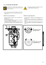
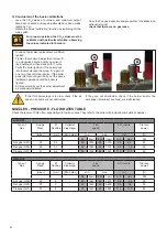
Page 27: ... 11 1 Once the burner is on check that the CO2 MAXIMUM value corresponds to that indicated in the table NOZZLES PRESSURE if it does not correspond correct it by turning the screw S CLOCKWISE to decrease it ANTICLOCKWISE to increase it 3 12 ADJUSTING THE BURNER 2 Minimum output adjustment Operate the boiler in calibration mode at MINIMUM OUTPUT see 3 11 1 Once the burner is on check that the CO2 MI...

Page 28: ...hragm Fan speed CO2 levels Start up power mbar mm Ø n holes min max FL rpm FH rpm min max IG Nat gas G20 20 9 20 1440 95 6850 9 5 9 5 50 Nat gas G25 25 9 20 1440 95 6850 9 5 9 5 50 Propane G31 37 9 20 1440 90 6500 11 0 11 0 60 If the CO2 percentage is too low check if the air and smoke ducts are not obstructed Check the levels of CO2 often especially with low flow rates They refer to the boiler wi...

Page 29: ...in heating mode by decreasing the burner pressure value 3 12 1 ADAPTATION OF THE POWER TO THE HEATING SYSTEM E g BWA R 50 to decrease the output of the boiler to 35 kW edit parameter HP about 72 Es BWA R 70 c to decrease the output of the boiler to 50 kW edit parameter HP about 76 Power Supply KW FH Act on parameter HP par 4 2 SE parameters list to achieve the value corresponding to the desired ou...

Page 30: ...osed previously Vent and if necessary restore the heating pressure until reaching a pressure of 0 8 1 0 bar Open the gas shut off valve Switch the boiler on Make sure the appliance is gas tight and watertight Failure to perform Inspections and Maintenance can entail material and personal damage TABLE OF RESISTANCE VALUES ACCORDING TO THE TEMPERATURE TO THE HEATING PROBE 11 sr and to the DOMESTIC H...

Page 31: ...eat the TL until it intervenes at 102 C and check that it intervenes at 102 DK safety pressure switch against water deficiency 13 Does the pressure switch block the boiler if the water pressure is below 0 4 bar Without request close the shut off valves of the heating circuit open the drain valve to make the water pressure de crease Before pressurising again check the pressure of the expansion vess...

Page 32: ...ise In that case contact the supplier of the LPG tank Gas Conversion The boilers are produced for the type of gas specifically requested upon ordering In order to change the gas one must change the Factory parameter FH and FL for values see TABLE NOZZLES PRESSURE FLOW when the conversion is complete fill in the information required on the label supplied in the documentation envelope and apply it n...

Page 33: ...ge value A Operation READING PARAMETER Press the YELLOW key to view default setting B Operazion CHANGE PARAMETER Press key PLUS MINUS to modify C Operazion SET MODIFY PARAMETER Press the YELLOW key eBUS IDENTIFICATION CODE eBUS IDENTIFICATION CODE VALUE FROM TO DEFAULT 0 10 0 BURNER MODULATION LEVEL IN IGNITION Continue with the modification of parameters by pressing the MINUS Repeat the operation...

Page 34: ...INUS Repeat the operations A B C to change value VALUE FROM TO DEFAULT 35 C 45 C 40 C SETTING OF THE MAXIMUM HEATING TEMPERATURE Continue with the modification of parameters by pressing the MINUS Repeat the operations A B C to change value VALUE FROM TO DEFAULT 65 C 85 C 80 C SETTING OF THE MAXIMUM DHW TEMPERATURE only if combined with an external storage tank Continue with the modification of par...

Page 35: ...ectrode E RIV Detection Elecrode MVD Diverter valve motor external tank MDV kit ACS Diverter valve motor DHW kit P F Pump BWA 50 NOT AVAIBLE PM Modulating Pump SR Flow heating sensor SRR Return heating sensor SS Domestic hot water probe TL Limit thermostat TF Smoke Thermostat Predisposition VG Gas Valve VM Modulating fan TA On off TA connection terminals BWA R 50 CAUTION THE KIT ACS BOILER MUST BE...

Page 36: ...erminals HSCP E8 E ACC Ignition Electrode E RIV Detection Elecrode MVD Diverter valve motor external tank MDV kit ACS Diverter valve motor DHW kit PM Modulating Pump SR Flow heating sensor SRR Return heating sensor SS Domestic hot water probe TL Limit thermostat TF Smoke Thermostat Predisposition VG Gas Valve VM Modulating fan TA On off TA connection terminals ...

Page 37: ... exchanger health encrusted E06 HIGH TEMPERATURE Over high temperature detected by the heating sensor SR 95 C Check the operation the pump and possi bly clean the heat exchanger 24 E05 Loss of flame signal during boiler operation Press the reset key on the panel E04 No flame detected during the ignition phase Press the reset key on the control panel E24 FAN SPEED OUT OF CONTROL Alteration of the f...

Page 38: ...s not clear replace the electrode 4 E20 FLAME PARASITE Flame detected after shutdown Check the wiring and leakage of the gas valve 3 eventually replace Gas Valve E10 Internal fault Replace the control board REQUEST FOR MAINTENANCE After 10 000 switching On or 2 000 hours of operation of the burner boiler needs servicing The blink code Sr does not preventthe normal operation of the boiler Service t...

Page 39: ......

Page 40: ...ers com www schusterboilers com The manufacturer declines every responsibility for the possible inaccuracies if owed to errors of transcript or press Also reserves the right to bring those changes that it will hold necessary to it own products or profits without jeopardizing its essential characteristics ...

Reviews: