background image

14

2.6 -  GENERAL FEATUREs swG P

OPERATING DATA ACCORDING TO UNI 10348 swG P 

Attention: should the boilers be used to heat systems at low temperature (e.g. radiant panels), a mixer valve is required to avoid 

condensation forming.

SWG

A 23 P

C 24 P

C 28 P

C 32 P

Maximum thermal flow rate

kW

25.5

26.5

30.1

34.5

Minimum thermal flow rate

kW

11.5

11.5

11.5

13.5

Effective nominal output

kW

22.9

24.7

28.1

32.3

Minimum effective output

kW

9.9

10.1

10.2

12.2

Effective efficiency at nominal load (100%)

%

89.8

93.05

93.21

93.5

Effective efficiency required (100%)

%

89.72

92.78

92.90

93.02

Effective efficiency at 30% load

%

89.43

90.43

90.42

90.42

Effective efficiency required (30%)

%

87.08

90.18

90.34

90.53

Number of stars (according to 92/42 EEC)

no.

Combustion 

 efficiency with nominal load (100%)

%

91.36

93.21

94.6

94.57

Combustion efficiency with reduced load

%

88.5

88.06

89.52

88.76

Heat loss at casing (min.-max.)

%

2.0- 1.6

0.17 - 0.16

0.77-1.40

1.07-1.35

(*) Flue gas temperature tf-ta (max.)

%

95.5

119.3

96.3

101.4

Flue gas mass flow rate (min.-max)

g/s

19.1-21.2

14.21-13.74

15.17-15.35

18.12-16.8

Excess λ air

%

140.7

45.15

42.56

35.34

CO

2

%

2.2-4.6

3.0-7.8

2.8-8.0

2.75-8.4

NOx

 (Weighted value according to EN 297/A3 or EN 483)

mg/kWh 189.2

184.16

186.00

164.05

NOx Class

2

2

2

2

 Heat loss at chimney

 with burner on (min.-max.)

%

8.6-11.5

11.94-6.79

5.40-10.48

5.40-11.2

Heat loss at chimney with burner off

%

0.657

0.256

0.321

0.280

(*) Room Temperature = 20°C

SWG

A 23 P

C 24 P

C 28 P 

C 32 P

Appliance category

II

2H3P

II

2H3P

II

2H3P


II

2H3P

Minimum heat. circuit output (∆t 20 °C)

l/min

7.1

7.2

7.3

8.7

Minimum heating circuit pressure

bar

0.5

0.5

0.5

0.5

Maximum heating circuit pressure

bar

3

3

3

3

Primary circuit content

l

3

3

3.5

3.5

Maximum operating temperature in heat. 

°C

78

78

78

78

Minimum operating temperature in heat. 

°C

45

45

45

45

Expansion vessel total capacity

l

6

6

8

10

Expansion vessel pre-load

bar

1

1

1

1

Maximum system capacity 

(max temp. calc. of 82°C)

l

138

138

184

230

Minimum domestic hot water circuit flow rate

l/min.

2.5

2.5

2.5

2.5

Minimum domestic hot water circuit pressure

bar

0.5

0.5

0.5

0.5

Maximum domestic hot water circuit pressure 

bar

6

6

6

6

Domestic hot water specific flow rate (∆t 30 °C)

l/min.

11

12

13.5

15.5

Domestic hot water flow rate limiter

l/min.

10

10

12

14

Production of D.H.W. in continuous operation with ∆t 45 K 

l/min.

7.8

7.4

 8.7

10.3

Production of D.H.W. in continuous operation with ∆t 40 K 

l/min.

8.8

8.3

9.8

11.6

Production of D.H.W. in continuous operation with ∆t 35 K 

l/min.

10.0

9.5

11.1

13.2

Production of D.H.W. in continuous operation with ∆t 30 K  

l/min.

11.7

11.0 

 13.0

15.4

Production of D.H.W. in continuous operation with ∆t 25 K (*)

l/min.

14.1

13.2

 15.6

18.5

Temperature adjustable in domestic hot water mode

°C

35-57

35-57

 35-57

35-57

Voltage/Frequency electric power supply

V-Hz

230/50

230/50

230/50

230/50

Fuse on the power supply

A (F)

2

2

2

2

Maximum absorbed output 

W

85

138

138

150

Protection rating

IP

X4D 

X5D 

X5D 

X5D 

Net weight

kg

28.6

30.1

35.2

36.2

Gross weight

kg

31.5

33

38.2

39.2

(*) mixed

Summary of Contents for SWG A 23

Page 1: ...SWG ENGLISH INSTALLATION AND SERVICING MANUAL A 23 R 23 A 23 P C 16 C 18 R18 C 24 R 24 C 24 P C 28 R 28 C 28 P C 32 C 32 P ...

Page 2: ...n to a special recycling centre managed by the local authorities or to a dealer who offers this service Separate disposal of a domestic appliance avoids possible negative consequences for the environment and human health deriving from inappropriate waste handling and allows the recovery of the materials of which it is made in order to obtain significant energy and resource savings ...

Page 3: ...hat can be edited from the control panel 30 4 3 Adaptation of the power to the heating system 31 4 4 Important notes 32 4 5 Wiring diagram 32 4 6 Error codes 34 3 INSTALLATION INSTRUCTIONS 15 3 1 General warnings 15 3 2 Installation standards 15 3 3 Preventive system verification and adjustment operations 15 3 4 Packaging 16 3 4 Positioning the boiler 17 3 6 Flue gas exhaust pipe connection 18 3 7...

Page 4: ...duct and must be kept by the user Read the warnings contained in this instruction booklet carefully as they provide important guidelines regarding installation use and maintenance safety Keep the booklet with care for further consultation Your appliance must be installed and serviced in compliance with the standards in force according to the manufacturer instructions up to standard and by legally ...

Page 5: ...hese instructions to the user as well as other documents concerning the appliance inserted in the envelope inside the packaging The user must keep this documentation safe for future consultation Inform the user about the importance of the air vents and the flue gas exhaust system high lighting their essential features and the absolute prohibition of modifying them Inform the user concerning contro...

Page 6: ...ete Do not modify the following parts the boiler the gas air water and electricity supply lines the flue gas pipe the safety valve and the exhaust pipe the construction parts which affect the operating safety of the appliance Attention To tighten or loosen the screwed fittings use only appropriate fixed spanners Incompliant use and or inappropriate tools can cause damage e g water or gas leakage A...

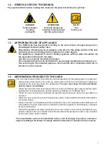
Page 7: ...densation 11 Qmax Maximum heat output 12 Adjusted Qn Adjusted for rated heat output 13 PMS Max heating operating pressure 14 T max Max heating temperature B Domestic hot water circuit characteristics 15 Qnw Rated heat output in domestic hot water function if different to Qn 16 D Specific D H W flow rate according to EN 625 EN 13203 1 17 R factor No of taps according to the declared amount of water...

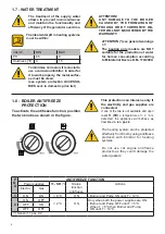
Page 8: ...arranty 1 8 BOILER ANTIFREEZE PROTECTION To activate the antifreeze function position the two knobs as shown in the figure This protection can intervene only if the electricity and gas supplies are connected If one of the two is not available and upon reset 11 SR a temperature of 2 C is detected the appliance will behave as described in tab pos 2 The heating system can be protected effectively fro...

Page 9: ...9 ENGLISH TECHNICAL FEATURES 2 TECHNICAL FEATURES AND DIMENSIONS 2 1 TECHNICAL FEATURES 2 2 VIEW WITH THE INDICATION OF THE MAIN COMPONENTS AND DIMENSIONS SWG A 23 SWG A 23 P SWG A 23 SWG R23 SWG A 23 P ...

Page 10: ...10 View from above View from below SWG C 24 P SWG C 18 SWG C 24 SWG C 16 SWG C 18 SWG R 18 SWG C 24 SWG R 24 SWG C 24 P ...

Page 11: ...11 ENGLISH TECHNICAL FEATURES View from above View from below SWG C 28 P SWG 32 P SWG C 28 SWG C 32 SWG C 28 SWG R 28 SWG C 28 P SWG C 32 SWG R 32 SWG C 32 P ...

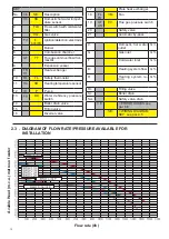
Page 12: ...Safety thermostat 11 Hb SR Heating temperature sensor 12 Ht P Pump 13 Lp DK Water deficiency pressure switch 14 Boiler drain valve 15 Filling valve 16 Diverter valve 17 Plate heat exchanger 18 FL FH VM Fan 19 AF AS PV Flue gas pressure switch 20 Safety valve 21 Automatic by pass C Domestic hot water outlet G G Gas inlet G F Cold water inlet G M Heating system flow G R Heating system re turn G Rc F...

Page 13: ... 0 354 0 457 0 354 0 32 0 280 Notes Room Temperature 20 C Data detected with appliance running on Methane gas G20 SWG A 23 R 23 C 16 C 18 R 18 C 24 R 24 C 28 R 28 C 32 Appliance category II2H3P II2H3P II2H3P II2H3P II2H3P II2H3P Minimum heat circuit output t 20 C l min 7 12 7 26 5 56 7 26 7 3 8 28 Minimum heating circuit pressure bar 0 5 0 5 0 5 0 5 0 5 0 5 Maximum heating circuit pressure bar 3 3...

Page 14: ...mperature 20 C SWG A 23 P C 24 P C 28 P C 32 P Appliance category II2H3P II2H3P II2H3P II2H3P Minimum heat circuit output t 20 C l min 7 1 7 2 7 3 8 7 Minimum heating circuit pressure bar 0 5 0 5 0 5 0 5 Maximum heating circuit pressure bar 3 3 3 3 Primary circuit content l 3 3 3 5 3 5 Maximum operating temperature in heat C 78 78 78 78 Minimum operating temperature in heat C 45 45 45 45 Expansion...

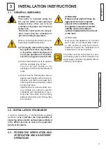
Page 15: ...en implemented to accommodate sev eral utilities according to specific standards and regulations in force Only after this check can the fitting between the boiler and chimney flue be mounted Attention If there is dust and or if there are aggressive corrosive vapours present in the installation room the appliance must be protected suitably and must be able to operate independently from the air in t...

Page 16: ...cturer will not be held liable for damage to persons animals or ob jects due to failure to comply with the instruction above H P L As well as the appliance the packaging contains A DOCUMENTATION ENVELOPE System booklet User operating instructions booklet Instruction booklet for the installer and maintenance engineer B Connection predisposition paper template C 2 rawlplugs for boiler attachment D F...

Page 17: ... R 24 SWG C 32 SWG C 24 28 32 P Since the temperature of the wall on which the boil er is installed and the temperature of the coaxial exhaust pipe do not exceed in normal operating conditions a room temperature beyond 60 K it is not necessary to observe the minimum distances from flammable walls For boilers with double intake and exhaust pipes in the event of crossing flammable walls insert insul...

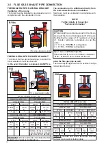
Page 18: ...s directed outside via coaxial or double pipes COAXIAL Ø80 125 DOUBLE Ø60 COLLECTOR COLLECTOR WITH WITHOUT WITH WITHOUT FROM m A m UP TO m FROM Cps A Cps UP TO Cps NA NA NA NA NA NA Distance between air inlet pipe and flue gas exhaust pipe min 250 mm max 500 Horizontal exhaust and intake terminals directed outside via coaxial or double pipes C12 C32 FOR BOILERS WITH FORCED DRAUGHT place the flue g...

Page 19: ...LECTOR COLLECTOR WITH WITHOUT WITH WITH OUT FROM Cps A Cps UP TO Cps FROM Cps A Cps UP TO Cps 1 1 8 8 40 20A 20S NA NA NA Separate combustion air intake and combustion products evacuation pipes These pipes can discharge into areas with different pressure C52 B22 ATTENTION The flue must comply with standards in force C62 Boiler intended for connection to a combustion air intake and combustion produ...

Page 20: ...s only with splitter systems KIT5570C 00361439 It is recommended to only use original exhaust pipes The supplier will have no contractual or extra contractual liability for damage caused due to incorrect installation and use and in any case failure to comply with the instructions provided by the manufacturer Adapter for double systems ...

Page 21: ...ualified installer who must re spect and apply that foreseen by relevant laws in force in the local prescriptions of the supply company Incorrect installation can cause damage to persons animals and objects for which the manufacturer cannot be held responsible If you smell gas a Do not operate electric switches the telephone or any other object that may cause sparks b Immediately open doors and wi...

Page 22: ... Connect the modulating thermostat wire between terminals TA1 OT after having removed the jumper ON OFF room thermostat connection RT OT Remember that a bipolar switch must be installed on the boiler power line with over 3 mm between contacts easy to access making maintenance quick and safe The power cable must be replaced by authorised technical staff using original spare parts only Failure to co...

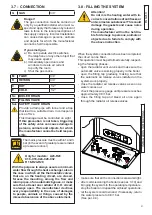
Page 23: ...on gas otherwise perform the boiler conversion in order to use the gas available see section 4 3 this operation must be carried out by technical staff qualified in compliance with the standards in force is the gas supply valve open has the system been checked for gas leaks is the outside main switch ON is the system safety valve efficient and is it connected to the drains has the system been check...

Page 24: ... is NOT authorised to ac 3 11 1 ACTIVATION OF THE calibration function 3 11 2 Positioning the probes 1 ACTIVATION By pressing the button D for 3 seconds the calibration function is activated Release it when the SERVICE symbol appears Do not press it for more than 9 This function is not activated if there is a block or domestic hot water request 2 MAXIMUM OUTPUT By turning the knob B onto MAX the b...

Page 25: ...switch Remove the flexible tube from the pressure gauge and close the pressure socket screw again Check that there are no gas leaks P Q R P R Q S 3 12 ADJUSTING THE BURNER 2 Minimum output adjustment Operate the boiler in calibration mode at MINI MUM OUTPUT see 3 11 1 Once the burner is on check that the MINIMUM pressure value corresponds to that indicated in the table NOZZLES PRESSURE Correct it ...

Page 26: ...e G31 10 1 24 6 11 5 26 5 37 0 85 11 6 1 33 5 0 89 kg h 2 06 kg h SWG R 28 SWG C 28 Type of Gas Furnace Useful kW Thermal Capacity kW Pressure Press mbar Ø Nozzles mm Nozzles no Ø Col lector mm Pressure minimum mbar Pressure operating mbar Consumption min Consumption max Nat gas G20 10 2 28 0 11 5 30 1 20 1 30 1 3 2 0 13 3 1 22 m h 3 18 m h Propane G31 10 2 28 0 11 5 30 1 37 0 85 13 4 4 29 0 0 89 ...

Page 27: ... 11 1 1 ACTIVATION Collect the pressure gauge differential to measure the burn er pressure see par 3 12 2 EDITING THE VALUE Modify parameter HP see par 4 2 until the value cor responding to the wanted power is obtained 3 CHECK Switch on the boiler in heating mode Check the pressure on the pressure gauge based on the requested power through the chart EDITING THE VALUE Turn the DOMESTIC HOT WATER kn...

Page 28: ...and if necessary restore the heating pres sure until reaching a pressure of 0 8 1 0 bar Open the gas shut off valve Switch the boiler back on Make sure the appliance is gas tight and water tight Remount the front casing of the appliance Failure to perform Inspections and Main tenance can entail material and personal damage TABLE OF RESISTANCE VALUES ACCORDING TO THE TEMPERATURE TO THE HEATING PROB...

Page 29: ...erheating Heat the TL until it intervenes at 95 C and check that it intervenes at 95 DK safety pressure switch against water deficiency 13 Does the pressure switch block the boiler if the water pressure is below 0 4 bar Without request close the shut off valves of the heating circuit open the drain valve to make the water pressure decrease Before pres surising again check the pressure of the expan...

Page 30: ...ULT 0 20 C 30 10 C 20 0 C NUMBER OF SWITCH ONS LIMIT DEVICE VALUES FROM A A DEFAULT 0 1 minute 15 minutes 0 WITH VARIABLE HYSTERESIS PUMP POST CIRCULATION VALUES FROM A DEFAULT 0 5 min 1 ALWAYS 0 5 min SELECTION Turn the HEATING knob B EDITING THE VALUE Turn the DOMESTIC HOT WATER knob C The value flashes on the display CONFIRM SELECTION Confirm the parameter to be edited by pressing the unblock k...

Page 31: ...e LPG supplier or a person qualified in compliance with law If the tank has not been professionally deaerated ignition problems could arise In that case contact the supplier of the LPG tank To convert the boiler from one type of gas to another proceed as follows Disconnect the appliance from the elctrical power supply disconnect the detection switch on electrode 1 loosen the 4 screws 2 that connec...

Page 32: ...ration must be performed with a cooled system The pressure gauge fitted on the boiler allows you to read the circuit pressure NOTE If the boiler was without electric power after a certain idle period the pump could be blocked Before electrically powering the boiler the pump must be unblocked by operating as follows Remove the protective screw from the pump centre using a cloth and insert a screwdr...

Page 33: ...lectrode FLS Domestic hot water request flow switch MVD Diverter valve motor SWG P Only P Pump PV Fan Pressure Switch SWG forced draught only SR Heating sensor SS DHW probe SWG C only TF Flue gas thermostat SWG natural draught only TL Limit thermostat VG Gas valve V Fan SE External probe connection terminals TA1 OT Modulating TA connection terminals TA2 On off TA connection terminals ...

Page 34: ...er freezing is detected If the heating sensor detects a temperature below 2 C burn er ignition is inhibited until the sensor detects a temperature above 5 C Disconnect the from the power supply close the gas valve defrost the exchanger careful ly 4 SAFETY THERMOSTAT Intervention of the safety ther mostat 10 Press the unblock button D on the panel and or check that the thermostat or its connections...

Page 35: ...t electrode and remove any oxidation press the un block key if the anomaly persists replace the electrode service 16 INTERNAL ERROR Replace the electronic board service 17 LOW VOLTAGE Power supply voltage too low service 19 ERROR CONFLICT FIRMWARE Replace the electronic board service 20 ERROR CIRCUIT FLAME Replace the electronic board service 21 ERROR DRIVER VALVE GAS Replace the electronic board ...

Page 36: ...oilers com www schusterboilers com The manufacturer declines every responsibility for the possible inaccuracies if owed to errors of transcript or press Also reserves the right to bring those changes that it will hold necessary to it own products or profits without jeopardizing its essential characteristics ...

Reviews: