6 Introduction
AV200pro
1.2.2
Ports
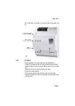
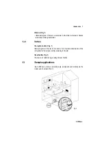
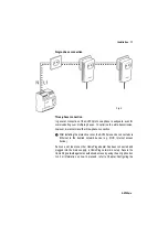
Line connections (Fig. 1)
This is where you connect the conductors to the corresponding line connec-
tions.
NOTE:
Single-phase connection: Neutral conductors and external conductors are
connected to terminals N and L1.
Three-phase connection: Neutral conductors and external conductors are
connected to terminals N and L1. The connection of external conductors L2
and L3 is optional and intended for optimising the signal transmission. The
device is supplied with power via terminals N and L1.
The permitted conductor cross-section for connection to the terminals is
0.18 mm² to 6 mm².
Ethernet connection (Fig. 1)
This is where you connect the AV200pro via an Ethernet cable to the intelli-
gent power meter (MUC) or another Ethernet device (e.g. Internet access
device).
1.2.3
Control lamps
Power (Fig.1)
•
Illuminates green when the AV200pro is ready to operate; flashes green
when the AV200pro is in standby mode.
HomePlug (Fig. 1)
•
Illuminates green if the bandwidth is optimal, i.e. the network connection is
suitable e.g. for HD video streaming; flashes when data is being transmit-
ted.
•
Illuminates orange if the bandwidth is good, i.e. the network connection is
suitable e.g. for SD video streaming; flashes when data is being transmit-
ted.
•
Illuminates red if the bandwidth is adequate, i.e. the network connection is
still suitable for transmission of energy data or Internet access; flashes
when data is being transmitted.


