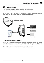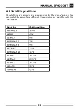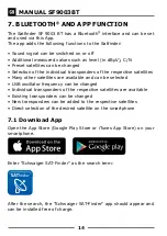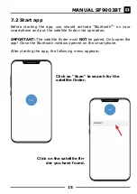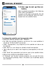
11
MANUAL SF9003BT
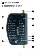
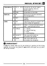
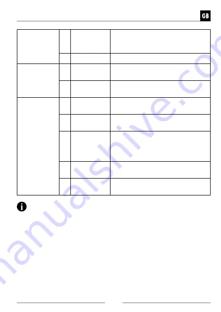
Connectors 1
DC 5 - 18 V Connection for power supply
(power adapter, receiver,
power bank ...)
2
LNB:
Connection to the LNB
Buttons
3
TP
Short press switches between
the transponders
4
SAT
Display
Position
LEDs
5
ON
Operating voltage is present, the
unit is ready for operation.
6
13/18 V
Yellow = Horizontal band active
Red = Vertical band active
7
DiSEqC
A = Yellow
B = Yellow flashing
C = Red
D = Red flashing
8
QUALITY
The more LEDs light up,
the better the quality
9
LEVEL
The more LEDs are lit,
the better the reception
IMPORTANT
If
only
the LEVEL LEDs are lit, the antenna is pointing at the wrong
satellite. Only when the QUALITY
and
LEVEL LEDs light up is a satel-
lite being received.

