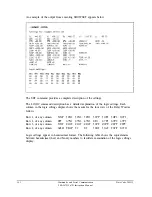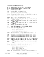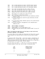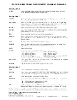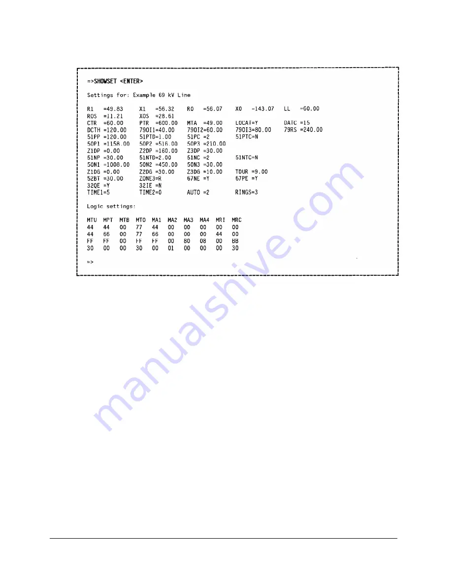
An example of the output from executing SHOWSET appears below:
The SET command provides a complete description of the settings.
The LOGIC command description has a detailed explanation of the logic settings. Each
column in the logic settings display shows the masks for the four rows of the Relay Word as
follows:
Row 1, of any column:
51NP
50N1
50N2
50N3
51PP
5OP1
5OP2
5OP3
Row 2, of any column:
DFP
67Nl
67N2
67N3
DFG
67Pl
67P2
67P3
Row 3, of any column:
51NT
Z1GT
Z2GT
Z3GT
51PT
ZlPT
Z2PT
Z3PT
Row 4, of any column:
ALRM
TRIP
TC
DT
52BT
52AT
TOCP
DCTH
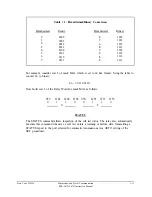
Logic settings appear in hexadecimal format. The following table shows the equivalencies
between hexadecimal (hex) and binary numbers to facilitate examination of the logic settings
display.
3-12
Commands and Serial Communication
SEL-267D/167D Instruction Manual
Date Code 940512
Summary of Contents for SEL-167D
Page 3: ......
Page 6: ......
Page 8: ......
Page 9: ......
Page 10: ......
Page 11: ......
Page 51: ...LOGIC DIAGRAMS Date Code 920326 Specifications SEL 267D 167D Instruction Manual 2 31 ...
Page 52: ...Date Code 920326 Specifications 2 32 SEL 267D 167D Instruction Manual ...
Page 53: ...Date Code 920326 Specifications SEL 267D 167D Instruction Manual 2 33 ...
Page 54: ...Date Code 920326 Specifications SEL 267D 167D Instruction Manual 2 34 ...
Page 88: ...SAMPLE EVENT REPORT ...
Page 114: ......
Page 115: ......


