INSTALLATION CHECKOUT
The following suggestions may be used or combined with your normal practice. In no case
should a recommendation be followed unless it is allowed by the rules of your normal
practice.
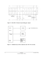
A portable terminal or computer is a convenient tool for providing local communications with
the SEL-267D relay during checkout in the field. Such a device should be connected to
PORT 2R or PORT 2F for checkout (with PORT 2 being designated as the automatic port
using the AUTO setting in the SET command).
1.
Apply control power and make sure the terminal displays the startup message. If not, set
AUTO = 2, using the SET command on Access Level 2. Check the settings with the
ACCESS and SHOWSET commands. Use the TIME and DATE commands to set the
clock and date.
2.
Apply three-phase voltages. Execute the METER command and verify that the readings
are accurate. If not, be sure the correct PT ratio was entered and recall that displayed
values are in primary line-to-neutral and line-to-line kV.
3.
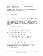
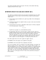
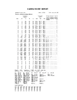
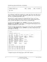
Use the TRIGGER command to save an event record. Type the EVENT 1 command
and examine the triggered event record. Referring to the top row of data as the
"
Y
"
components and the next row as the
"
X
"
components, plot the three voltage phasors to
ensure that they are 120 degrees apart, of reasonable magnitudes, and rotating in the
positive-sequence direction. The zero-sequence voltage Y and X components (times a
factor of three) are the total of the three Y components and the total of the three X
components. These sums should be near zero if balanced three-phase potentials are
present.
4.
Use the TARGET command to check the state of all contact inputs and outputs. For
example, if the connections to the circuit breaker 52A contact are made when the circuit
breaker is closed, the TARGET command with option 5 should show a one (1) under the
52A heading (type TARGET 5 <ENTER>).
5.
Proceed to Access Level 2 with the 2ACCESS command and appropriate password. Be
sure that the ALARM relay contacts close and open when the 2ACCESS command is
executed (The ALARM pulse will not be detectable if the ALARM contacts are perma-
nently asserted due to any other alarm condition).
6.
The tripping function may be tested in any of three ways. First, be sure the circuit
breaker can be tripped by the SEL-267D relay when you execute the OPEN command.
Be sure the TC bit is set in the MTU mask. Second, the circuit breaker should trip when
you assert the DIRECT TRIP input, assuming that the DT bit is selected in the MTU
mask. The TRIP output relay opens in both of these cases after the 52A input is
deasserted, indicating that the circuit breaker has indeed opened. This function of
monitoring the 52A contact ensures that the output relay does not inadvertently open
while trip coil current is flowing in response to a control operation. Third, the circuit
breaker should trip when you apply voltages and currents representing a fault condition
5-6
Installation
SEL-267D Instruction Manual
Date Code 920326
Summary of Contents for SEL-167D
Page 3: ......
Page 6: ......
Page 8: ......
Page 9: ......
Page 10: ......
Page 11: ......
Page 51: ...LOGIC DIAGRAMS Date Code 920326 Specifications SEL 267D 167D Instruction Manual 2 31 ...
Page 52: ...Date Code 920326 Specifications 2 32 SEL 267D 167D Instruction Manual ...
Page 53: ...Date Code 920326 Specifications SEL 267D 167D Instruction Manual 2 33 ...
Page 54: ...Date Code 920326 Specifications SEL 267D 167D Instruction Manual 2 34 ...
Page 88: ...SAMPLE EVENT REPORT ...
Page 114: ......
Page 115: ......


