3-12
Auxiliary Function Settings
Date Code 20060731
SEL-300G Instruction Manual
DWG: M300G083
(-)
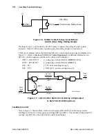
SCADA
Switch Active Setting Group
(+)
IN104
SEL-300G
Figure 3.6: SCADA Contact Pulses Input IN104 to
Switch Active Relay Setting Groups
If setting Group 1 is active and the SCADA contact is pulsed, the setting Group 2 is then
activated. If the SCADA contact is pulsed again, the setting Group 1 is reactivated.
This logic is implemented in the following SEL
OGIC
control equation settings and displayed in
Figure 3.7. (Refer to
Section 4: SEL
OGIC
Control Equations
for additional information on
control equations and the latch control switch function.)
SET5 = /IN104*!LT5
[= (rising edge of input IN104)
AND
NOT(LT5)]
RST5 = /IN104*LT5
[= (rising edge of input IN104)
AND
LT5]
SS1 = LT5
[= LT5; activate setting Group 1]
SS2 = !LT5
[= NOT(LT5); activate setting Group 2]
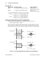
DWG: M300G084
LT5
IN104
(set)
(reset)
rising edge
detect
SET5
Relay
Word
Bit
RST5
SEL
OGIC
Setting
SEL
OGIC
Setting
Relay
Word
Bit
Figure 3.7: Latch Control Switch Controlled by a Single Input
to Switch Active Setting Group
Feedback Control
Note in Figure 3.7 that the latch control switch output (latch bit LT5) is effectively used as
feedback for SEL
OGIC
control equation settings SET5 and RST5. The feedback of latch bit LT5
“guides” input IN104 to the correct latch control switch input.
Summary of Contents for SEL-300G
Page 1: ...SEL 300G Multifunction Generator Relay Instruction Manual 20060731 PM300G 01 NB ...
Page 4: ......
Page 6: ......
Page 138: ......
Page 166: ......
Page 170: ......
Page 288: ......
Page 290: ......
Page 328: ......
Page 442: ......
Page 456: ......
Page 458: ......
Page 468: ......
Page 470: ......
Page 512: ......
Page 516: ......
Page 518: ......
Page 552: ......
Page 554: ......
Page 560: ......
Page 578: ......
Page 626: ......
Page 724: ......
Page 728: ......


