4-40 SEL
OGIC
Control Equations
Date Code
20060731
SEL-300G Instruction Manual
Table 4.3: Correspondence Between Local Control
Switch Positions and Label Settings
Switch Position
Label
Setting
Setting Definition
Logic State
Not applicable
NLB
n
Name of Local Control
Switch
not applicable
ON SLB
n
“Set” Local bit LB
n
logical
1
OFF CLB
n
“Clear” Local bit LB
n
logical
0
MOMENTARY PLB
n
“Pulse” Local bit LB
n
logical 1 for one processing
interval
Note the first setting in Table 4.3 (NLB
n
) is the overall switch name setting. Make each label
setting through the serial port using the command
SET G
. View these settings using the serial
port command
SHO G
(see
Section 6: Enter Relay Settings
and
Section 10: Serial Port
Communications and Commands
).
Local Control Switch Types
Configure any local control switch as one of the following three switch types.
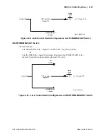
ON/OFF Switch
Local bit LB
n
is in either the ON (LB
n
= logical 1) or OFF (LB
n
= logical 0) position.
OFF position
(logical 0)
ON
position
DWG: M300G144
Relay
Word
Bit
LBn
Logical 1
(n=1 through 16)
Figure 4.19: Local Control Switch Configured as an ON/OFF Switch
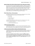
OFF/MOMENTARY Switch
The local bit LB
n
is maintained in the OFF (LB
n
= logical 0) position and pulses to the
MOMENTARY (LB
n
= logical 1) position for one processing interval (1/4 cycle).
Summary of Contents for SEL-300G
Page 1: ...SEL 300G Multifunction Generator Relay Instruction Manual 20060731 PM300G 01 NB ...
Page 4: ......
Page 6: ......
Page 138: ......
Page 166: ......
Page 170: ......
Page 288: ......
Page 290: ......
Page 328: ......
Page 442: ......
Page 456: ......
Page 458: ......
Page 468: ......
Page 470: ......
Page 512: ......
Page 516: ......
Page 518: ......
Page 552: ......
Page 554: ......
Page 560: ......
Page 578: ......
Page 626: ......
Page 724: ......
Page 728: ......


