4-56 SEL
OGIC
Control Equations
Date Code
20060731
SEL-300G Instruction Manual
Circuit Breaker Wear Monitor
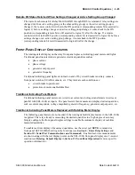
The SEL-300G circuit breaker wear monitor function described in
Section 3: Auxiliary
Function Settings
provides an indication, BCW, when the combination of close-to-open
operations and interrupted current exceeds the breaker manufacturer’s wear recommendation, as
entered into the relay via the settings. To provide an annunciator indication that the circuit
breaker wear rating has been exceeded, add the BCW Relay Word bit to the protection alarm
annunciator contact SEL
OGIC
control equation:
OUT107 = … + BCW + …
DC Voltage Monitor
Section 3: Auxiliary Function Settings
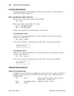
offers several examples of methods to indicate that the
dc voltage applied to the relay is outside normal bounds. To cause OUT107 to close while the dc
voltage is out of tolerance, but still high enough that the relay is operable, add the following
statement to the OUT107 SEL
OGIC
control equation:
OUT107 = …+ !(DCLO * DCHI) + …
With the setting DCHIP set below normal dc voltage and DCLOP set above normal dc voltage,
OUT107 will close if the dc voltage rises above DCLOP or falls below DCHIP. If dc voltage
fails altogether, the relay ALARM contact will close.
Relay Self-Test Alarms
The relay runs a variety of self-tests. As shown below, many relay problems detected by self-test
cause a closure of the ALARM output contact. Monitoring this contact is the single most
important relay maintenance activity that you can perform.
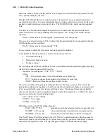
The relay takes the following corrective actions for out-of-tolerance conditions (see Table 4.5):
•
Protection Disabled: The relay disables all protection functions and trip/close logic. All
output contacts are de-energized. The EN front-panel LED is extinguished.
•
ALARM Output: The ALARM output contact signals an alarm condition by going to its
de-energized state. If the ALARM output contact is a “b” contact (normally closed), it
closes for an alarm condition or if the relay is de-energized. If the ALARM output
contact is an “a” contact (normally open), it opens for an alarm condition or if the relay
is de-energized. Alarm condition signaling can be a single 5-second pulse (Pulsed) or
permanent (Latched).
•
The relay generates automatic STATUS reports at the serial port for warnings and
failures.
•
The relay displays messages on the LCD display for failures.
Use the serial port
STATUS
command or front-panel STATUS pushbutton to view relay self-test
status.
Summary of Contents for SEL-300G
Page 1: ...SEL 300G Multifunction Generator Relay Instruction Manual 20060731 PM300G 01 NB ...
Page 4: ......
Page 6: ......
Page 138: ......
Page 166: ......
Page 170: ......
Page 288: ......
Page 290: ......
Page 328: ......
Page 442: ......
Page 456: ......
Page 458: ......
Page 468: ......
Page 470: ......
Page 512: ......
Page 516: ......
Page 518: ......
Page 552: ......
Page 554: ......
Page 560: ......
Page 578: ......
Page 626: ......
Page 724: ......
Page 728: ......


