2-6
Relay Element Settings
Date Code 20060731
SEL-300G Instruction Manual
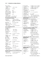
Differential (IA87, IB87, IC87) CT Ratio (1–10000; 5 A models)
CTRD = 100
(1–50000; 1 A models)
Neutral (IN) CT Ratio (1–10000)
CTRN = 100
Phase (VA, VB, VC) PT Ratio (1.00–10000.00)
PTR = 100.00
Neutral (VN) PT Ratio (1.00–10000.00)
PTRN = 100.00
Synch-Voltage (VS) PT Ratio (1.00–10000.00)
PTRS = 100.00
Protection instrument transformer ratio settings allow the relay to display meter and
event report quantities in primary amperes, kilovolts, megawatts, and megavars. Enter
these settings as a ratio to one. For instance, a 1000:5-phase current transformer ratio
yields CTR = 200.
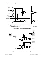
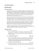
Figure 2.3 illustrates selection of the CTRN and PTRN settings. When a neutral
current transformer is connected directly in the generator neutral circuit, set CTRN
equal to the current transformer ratio to one.
In applications where the neutral current transformer is connected in the grounding
transformer secondary circuit, set CTRN equal to current transformer ratio to one. The
relay will report the current in the grounding transformer secondary rather than the
generator primary neutral current.
In high-impedance grounded applications, the relay VN input can be directly connected
to the generator grounding transformer secondary if neutral voltages during ground
faults will not exceed 300 Vac. When directly connected, set PTRN equal to the
grounding transformer voltage ratio to one. If an auxiliary transformer is connected
between the grounding transformer secondary and the relay, calculate PTRN by
multiplying the grounding transformer ratio by the auxiliary transformer ratio to one.
In resistance grounded applications, calculate PTRN directly using the neutral voltage
transformer ratio to one.
The synchronism checking PT may be connected phase-to-phase or phase-to-ground on
the system side of the generator circuit breaker. Select a PT ratio so the voltage
presented to the relay is nominally equal to the phase-to-phase or phase-to-ground
voltage presented to the relay by the generator PTs. The relay does not require that the
synchronism PT connection match the generator PT connection. For instance, you may
elect to use open-delta connected generator PTs and a phase-to-ground connected
synchronism PT.
Nominal Machine Voltage (80.0–140.0 V l-l, 3-wire delta voltage input)
VNOM = 115.0
(80.0–208.0 V l-l, 4-wire wye voltage input)
Calculate VNOM by dividing the generator rated line-to-line voltage by the phase
transformer ratio, PTR. In a typical 13.8 kV generator application, when PTR = 120,
VNOM = 115. The relay volts/hertz, voltage-restrained overcurrent, and directional
power elements use the VNOM setting.
Nominal Machine Current (1.0–10.0 A; 5 A Models)
INOM = 5.0
(0.2–2.0 A; 1 A Models)
Summary of Contents for SEL-300G
Page 1: ...SEL 300G Multifunction Generator Relay Instruction Manual 20060731 PM300G 01 NB ...
Page 4: ......
Page 6: ......
Page 138: ......
Page 166: ......
Page 170: ......
Page 288: ......
Page 290: ......
Page 328: ......
Page 442: ......
Page 456: ......
Page 458: ......
Page 468: ......
Page 470: ......
Page 512: ......
Page 516: ......
Page 518: ......
Page 552: ......
Page 554: ......
Page 560: ......
Page 578: ......
Page 626: ......
Page 724: ......
Page 728: ......


