7-32
Inputs, Outputs, Timers, and Other Control Logic
Date Code 20011205
SEL-311A Instruction Manual
Note that Figure 7.25 suggests the option of having output contacts OUT103 and OUT104
operate as additional breaker failure trip outputs. This is done by making the following SEL
OGIC
control equation settings:
OUT103 = SV7T
(breaker failure trip)
OUT104 = SV7T
(breaker failure trip)
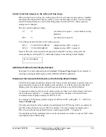
Additional Settings Example 2
The seal-in logic circuit in the dedicated breaker failure scheme in Figure 7.25 can be removed
by changing the SEL
OGIC
control equation setting SV7 to:
SV7 = IN101 * (50P1 + 50G1)
If the seal-in logic circuit is removed, optoisolated input IN101 (breaker failure initiate) has to be
continually asserted for a breaker failure time-out.
Timers Reset When Power Is Lost, Settings Are Changed, or Active Setting Group Is
Changed
If power is lost to the relay, settings are changed (for the active setting group), or the active
setting group is changed, the SEL
OGIC
control equation variables/timers are reset. Relay Word
bits SV
n
and SV
n
T (
n
= 1 through 16) are reset to logical 0 and corresponding timer settings
SV
n
PU and SV
n
DO load up again after power restoration, settings change, or active setting
group switch.
Preceding Figure 7.25 shows an effective seal-in logic circuit, created by use of Relay Word bit
SV7 (SEL
OGIC
control equation variable SV7) in SEL
OGIC
control equation SV7:
SV7 = (SV7 + IN101) * (50P1 + 50G1)
If power is lost to the relay, settings are changed (for the active setting group), or the active
setting group is changed, the seal-in logic circuit is “broken” by virtue of Relay Word bit SV7
being reset to logical 0 (assuming input IN101 is not asserted). Relay Word bit SV7T is also
reset to logical 0, and timer settings SV7PU and SV7DO load up again.
O
UTPUT
C
ONTACTS
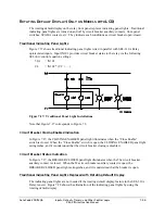
Figure 7.26 shows the operation examples of output contact Relay Word bits due to:
SEL
OGIC
control equation operation
or
PULSE
command execution
The output contact Relay Word bits in turn control the output contacts.
Alarm logic/circuitry controls the ALARM output contact (see Figure 7.26).
Summary of Contents for SEL-311A
Page 6: ......
Page 8: ......
Page 10: ......
Page 24: ......
Page 40: ......
Page 66: ......
Page 96: ......
Page 98: ......
Page 112: ......
Page 114: ......
Page 122: ......
Page 170: ......
Page 202: ......
Page 204: ......
Page 246: ......
Page 248: ......
Page 286: ......
Page 290: ......
Page 304: ......
Page 306: ......
Page 334: ......
Page 384: ......
Page 386: ......
Page 394: ......
Page 398: ......
Page 402: ......
Page 404: ......
Page 410: ......
Page 412: ......
Page 426: ......
Page 444: ......
Page 460: ......
Page 474: ......


