Date Code 20011205
Installation
2-5
SEL-311B Instruction Manual
M
AKING
R
EAR
-P
ANEL
C
ONNECTIONS
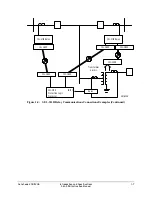
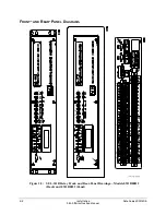
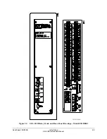
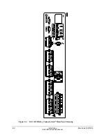
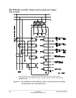
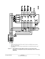
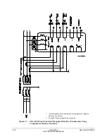
Refer to Figure 2.5 through Figure 2.7 for wiring examples of typical applications.
Tools: Phillips or slotted-tip screwdriver
Parts:
All screws are size #6-32. Locking screws can be requested from the factory.
Ground the relay chassis at terminal Z27.
Wire-Alike Screw Terminal Connections
All SEL-311B relays have SEL-221 wire-alike terminals. Both SEL-311B standard terminal
numbers and SEL-221 terminal numbers are shown on the rear-panel wiring connections for
those models. A properly programmed SEL-311B Relay may be installed in place of an SEL-221
Relay with no changes to the terminal numbers in a user’s wiring diagram.
Power Supply
Connect control voltage to the POWER terminals. Note the polarity indicators on terminals
Z25(+) and Z26(-). Control power passes through these terminals to a fuse and to the switching
power supply. The control power circuitry is isolated from the relay chassis ground.
Refer to
Section 1: Introduction and Specifications
for power supply ratings. The relay power
supply rating is listed on the serial number sticker on the relay rear panel.
Output Contacts
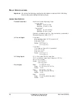
The contact outputs in the SEL-311B Relay are not polarity dependant. Refer to
General
Specifications
in
Section 1: Introduction and Specifications
for contact output ratings.
Optoisolated Inputs
The optoisolated inputs in the SEL-311B Relay are not polarity dependent. With nominal
control voltage applied, each optoisolated input draws approximately 4 mA of current. Refer to
General Specifications
in
Section 1: Introduction and Specifications
for optoisolated input
ratings.
Refer to the serial number sticker on the relay rear panel for the optoisolated input voltage rating.
Current Transformer Inputs
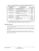
Note the polarity dots above terminals Z01, Z03, Z05, and Z07. Refer to Figure 2.5 through
Figure 2.7 for typical CT wiring examples.
Refer to the serial number sticker on the relay rear panel for the nominal current ratings (5 A or
1 A) for the phase (IA, IB, IC) and polarizing current inputs.
Summary of Contents for SEL-311B
Page 6: ......
Page 8: ......
Page 10: ......
Page 24: ......
Page 26: ......
Page 122: ......
Page 124: ......
Page 138: ......
Page 168: ......
Page 172: ......
Page 254: ......
Page 282: ......
Page 306: ......
Page 348: ......
Page 364: ......
Page 366: ......
Page 448: ......
Page 460: ......
Page 466: ......
Page 476: ......
Page 482: ......
Page 494: ......
Page 500: ......
Page 522: ......
Page 526: ......
Page 528: ......
Page 534: ......
Page 536: ......
Page 550: ......
Page 570: ......
Page 586: ......
Page 600: ......

