Date Code 20011205
Standard Event Reports and SER
12-3
SEL-311B Instruction Manual
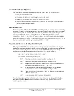
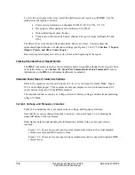
Rising edge operators are especially useful in generating an event report at fault inception and
then generating another later if for example a breaker failure condition occurs. If at the inception
of a ground fault, pickup indicator 51G asserts and an event report is generated:
ER = ... + /51G + ... = logical 1 (for one processing interval)
Even though the 51G pickup indicator will remain asserted for the duration of the ground fault,
the rising edge operator / in front of 51G (/51G) causes setting ER to be asserted for only one
processing interval. Other operators in the setting ER SEL
OGIC
control equation can trigger
event reports while 51G is still asserted.
Falling edge operators \ are also used to generate event reports. See Figure G.2 in
Appendix G:
Setting SEL
OGIC
Control Equations
for more information on falling edge operators.
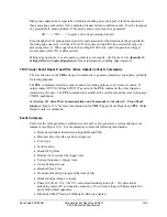
TRI (Trigger Event Report) and PUL (Pulse Output Contact) Commands
The sole function of the
TRI
serial port command is to generate standard event reports, primarily
for testing purposes.
The
PUL
command asserts the output contacts for testing purposes or for remote control. If
output contact OUT101 through OUT107 asserts via the
PUL
command, the relay triggers a
standard event report. The
PUL
command is available at the serial port and the relay front-panel
CNTRL pushbutton.
See
Section 10: Serial Port Communications and Commands
and
Section 11: Front-Panel
Interface
(Figure 11.3) for more information on the
TRI
(Trigger Event Report) and
PUL
(Pulse
Output Contact) commands.
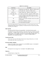
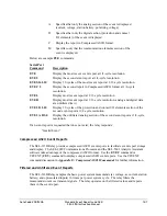
Event Summary
Each time the relay generates a standard event report, it also generates a corresponding event
summary (see Figure 12.1). Event summaries contain the following information:
·
Relay and terminal identifiers (settings RID and TID)
·
Date and time when the event was triggered
·
Event type
·
Fault location
·
Breaker Trip Time
·
Recloser shot count at the trigger time
·
System frequency at trigger time
·
Active Settings Group
·
Breaker Close Time
·
Front-panel fault type targets at the time of trip
·
Breaker Status (Open or closed)
·
Phase (IA, IB, IC, VA, VB, VC), calculated residual ground (I
G
= 3I
0
), directional
polarizing current IP, and negative-sequence (3I
2
) currents, along with phase angles for
pre-fault and fault quantities.
·
M
IRRORED
B
ITS
™ status if M
IRRORED
B
ITS
are enabled.
Summary of Contents for SEL-311B
Page 6: ......
Page 8: ......
Page 10: ......
Page 24: ......
Page 26: ......
Page 122: ......
Page 124: ......
Page 138: ......
Page 168: ......
Page 172: ......
Page 254: ......
Page 282: ......
Page 306: ......
Page 348: ......
Page 364: ......
Page 366: ......
Page 448: ......
Page 460: ......
Page 466: ......
Page 476: ......
Page 482: ......
Page 494: ......
Page 500: ......
Page 522: ......
Page 526: ......
Page 528: ......
Page 534: ......
Page 536: ......
Page 550: ......
Page 570: ......
Page 586: ......
Page 600: ......


