13-18
Testing and Troubleshooting
Date Code 20011205
SEL-311B Instruction Manual
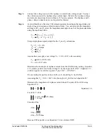
Step 5.
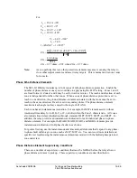
Determine the signals required to operate the element. For unsupervised elements,
simply use the following equations. Fulfilling the requirements of the supervisory
conditions may be more complicated. Refer to the test procedures appropriate to the
supervising element for details.
Step 6.
Apply the test signals.
Step 7.
Monitor the output contact assigned to indicate the state of the element under test to
ensure that the element asserts. Review the event reports to ensure that supervisory
conditions and the element under test asserted appropriately.
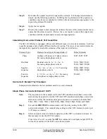
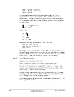
Calculating Overcurrent Element Test Quantities
The SEL-311B Relay is equipped with several different types of overcurrent elements. Each has
a specific purpose and a slightly different method of testing. The types of overcurrent elements,
the signals they operate from, and the elements of that type are listed below.
Element Type
Operates based upon the magnitude of: Relay
Elements
Phase
A-phase or B-phase or C-phase current.
Test using single-phase current.
50P1, 50P2, 50P3
Residual
Residual current: I
R
= I
A
+ I
B
+ I
C
.
Test using single-phase current.
50G1, 50G2, 50G3,
50G4, 50GF, 50GR
Negative-
Sequence
3 • I
2
= (I
A
+ a
2
• I
B
+ a • I
C
) Test using
single-phase current.
50Q1, 50Q2, 50Q3,
50Q4, 50QF, 50QR
Positive-
Sequence
I
1
= 1/3 (I
A
+ a • I
B
+ a
2
• I
C
) Test using
three-phase or single-phase current.
50ABC
Overcurrent Element Test Examples
Examples below illustrate the test methods used for several elements.
Single-Phase Overcurrent Element: 50P1
Note:
The steps taken in the example test for the 50P1 nondirectional phase overcurrent
element may be applied to test the 50P2 and 50P3 nondirectional phase overcurrent
element as well as the residual and negative-sequence overcurrent elements 50G1,
50G2, 50G3, 50G4, 50GF, 50GR, 50Q1, 50Q2, 50Q3, 50Q4, 50QF, and 50QR.
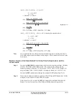
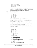
Step 1.
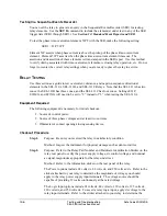
Execute the
SHOWSET
command and verify the relay setting for the 50P1
overcurrent element. The example relay settings set the 50P1 element to pick up at
11.25 amps, secondary.
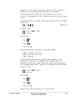
Step 2.
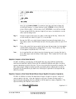
Select an output contact to indicate operation of the 50P1 overcurrent element. In
this example we use the OUT106 output.
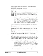
From Access Level 2, execute the
SET L n
command to configure output OUT106
to close for assertion of the 50P1 overcurrent element.
Summary of Contents for SEL-311B
Page 6: ......
Page 8: ......
Page 10: ......
Page 24: ......
Page 26: ......
Page 122: ......
Page 124: ......
Page 138: ......
Page 168: ......
Page 172: ......
Page 254: ......
Page 282: ......
Page 306: ......
Page 348: ......
Page 364: ......
Page 366: ......
Page 448: ......
Page 460: ......
Page 466: ......
Page 476: ......
Page 482: ......
Page 494: ......
Page 500: ......
Page 522: ......
Page 526: ......
Page 528: ......
Page 534: ......
Page 536: ......
Page 550: ......
Page 570: ......
Page 586: ......
Page 600: ......


