H-12
Distributed Network Protocol (DNP) 3.00
Date Code 20011205
SEL-311B Instruction Manual
from the corresponding index in the 0–499 group. Only points that are actually in the SER list
(
SET R
) will generate events in the 500–999 group.
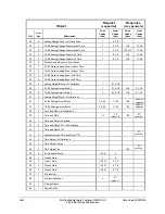
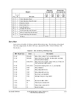
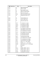
Analog Inputs (objects 30 and 32) are supported as defined by the preceding table. The values
are reported in primary units. Analog inputs 28–35, 42–57, 63–78, 84–102, and 104 are further
scaled according to the DECPLM setting (e.g., if DECPLM is 3, then the value is multiplied by
1000). Analog inputs 58–62, 79–83, and the even-numbered points in 0–7 and 16–21 (current
magnitudes) are scaled according to the DECPLA setting. The even-numbered points in 8–15
and 22–27 (voltage magnitudes) are scaled according to the DECPLV setting. Analog inputs 36–
41, 106, and the odd-numbered points in 0–27 (angles) are scaled by 100. The remaining analogs
are not scaled.
Event-class messages are generated whenever an input changes beyond the value given by the
ANADB setting. The dead-band check is done after any scaling is applied. The angles (the odd
numbered points in 0–27) will only generate an event if, in addition to their dead-band check, the
corresponding magnitude (the preceding point) contains a value greater than the value given by
the ANADB setting. Analog inputs are scanned at approximately a 1-second rate, except for
analogs 103–111. During a scan, all events generated will use the time the scan was initiated.
Analogs 103–111 are derived from the history queue data for the most recently read fault and do
not generate event messages. Analog 103 is a 16-bit composite value, where the upper byte is
defined as follows:
Value Event
Cause
1
Trigger command
2
Pulse command
4
Trip element
8
ER element
And the lower byte is defined as follows:
Value Fault
Type
0
Indeterminate
1
A-Phase
2
B-Phase
4
C-Phase
8
Ground
The lower byte may contain any combination of the above bits (e.g., a 6 is a B to C fault and a 9
is an A to Ground fault). If Analog 103 is 0, fault information has not been read and the related
analogs (104–111) do not contain valid data.
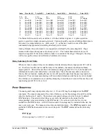
Control Relay Output Blocks (object 12, variation 1) are supported. The control relays
correspond to the remote bits and other functions, as shown above. The Trip/Close bits take
precedence over the control field. The control field is interpreted in the following table.
Summary of Contents for SEL-311B
Page 6: ......
Page 8: ......
Page 10: ......
Page 24: ......
Page 26: ......
Page 122: ......
Page 124: ......
Page 138: ......
Page 168: ......
Page 172: ......
Page 254: ......
Page 282: ......
Page 306: ......
Page 348: ......
Page 364: ......
Page 366: ......
Page 448: ......
Page 460: ......
Page 466: ......
Page 476: ......
Page 482: ......
Page 494: ......
Page 500: ......
Page 522: ......
Page 526: ......
Page 528: ......
Page 534: ......
Page 536: ......
Page 550: ......
Page 570: ......
Page 586: ......
Page 600: ......

