4-26
Loss-of-Potential, CCVT Transient Detection,
Date Code 20010625
Load-Encroachment, and Directional Element Logic
SEL-311L Instruction Manual
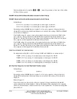
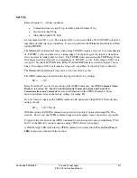
directional elements to be enabled (
0
2
I
•
2
.
0
I
>
). Again, this presumes at least one of the enables
32VE or 32IE is asserted.
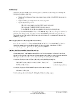
50GFP—Forward Directional Residual Ground Current Pickup
50GRP—Reverse Directional Residual Ground Current Pickup
Setting Range:
0.25–5.00 A secondary (5 A nominal phase current inputs, IA, IB, IC)
0.05–1.00 A secondary (1 A nominal phase current inputs, IA, IB, IC)
If preceding setting ORDER does not contain V or I (no zero-sequence voltage-polarized or
channel IP current-polarized directional elements are enabled), then settings 50GFP and 50GRP
are not made or displayed.
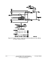
The 50GFP setting (3I
0
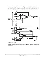
current value) is the pickup for the forward fault detector 50GF of the
zero-sequence voltage-polarized and channel IP current-polarized directional elements (see
Figure 4.7). Ideally, the setting is above normal load unbalance and below the lowest expected
zero-sequence current magnitude for unbalanced forward faults.
The 50GRP setting (3I
0
current value) is the pickup for the reverse fault detector 50GR of the
zero-sequence voltage-polarized and channel IP current-polarized directional elements (see
Figure 4.7). Ideally, the setting is above normal load unbalance and below the lowest expected
zero-sequence current magnitude for unbalanced reverse faults.
50GFP and 50GRP Set Automatically
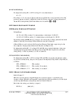
If configuration setting E32 = AUTO, settings 50GFP and 50GRP are set automatically at:
50GFP = 0.50 A secondary (5 A nominal phase current inputs, IA, IB, IC)
50GRP = 0.25 A secondary (5 A nominal phase current inputs, IA, IB, IC)
50GFP = 0.10 A secondary (1 A nominal phase current inputs, IA, IB, IC)
50GRP = 0.05 A secondary (1 A nominal phase current inputs, IA, IB, IC)
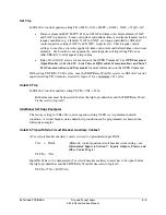
a0—Positive-Sequence Current Restraint Factor, |I
0
|/|I
1
|
Setting Range:
0.02–0.50 (unitless)
If preceding setting ORDER does not contain V or I (no zero-sequence voltage-polarized or
channel IP current-polarized directional elements are enabled), then setting a0 is not made or
displayed.
Refer to Figure 4.7.
The a0 factor increases the security of the zero-sequence voltage-polarized and channel IP
current-polarized directional elements. It keeps the elements from operating for zero-sequence
current (system unbalance), which circulates due to line asymmetries, CT saturation during three-
phase faults, etc.
Summary of Contents for SEL-311L
Page 6: ......
Page 8: ......
Page 26: ......
Page 54: ......
Page 144: ......
Page 216: ......
Page 252: ......
Page 302: ......
Page 338: ......
Page 480: ......
Page 484: ......
Page 486: ......
Page 502: ......
Page 532: ...12 28 Standard Event Reports and SER Date Code 20010625 SEL 311L Instruction Manual 4 ...
Page 552: ......
Page 554: ......
Page 574: ......
Page 576: ......
Page 596: ......
Page 602: ......
Page 628: ......
Page 656: ......
Page 662: ......
Page 664: ......
Page 688: ......
Page 700: ......
Page 716: ......
Page 722: ......
Page 734: ......

