5-36
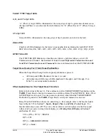
Trip and Target Logic
Date Code 20010625
SEL-311L Instruction Manual
LED
Number
LED Label
Definition
14
2
Zone/Level 2 element picked up at time of trip
15
3
Zone/Level 3 element picked up at time of trip
16
87CH FAIL Line current differential channel failure
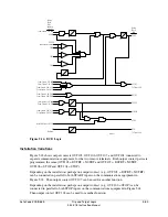
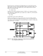
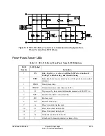
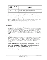
Target LEDs numbered 2 through 6 and 9 through 15 in Table 5.1 are updated and then latched
for every new assertion (rising edge) of the TRIP Relay Word bit. The TRIP Relay Word bit is
the output of the backup protection trip logic (see Figure 5.4). The TRIP Relay Word bit also
asserts when setting EHST
x
N and Relay Word bit TRIP87 asserts. The TRIP87 Relay Word
bit is the output of the 87L trip logic (see Figure 5.1).
Further target LED information follows. Refer also to Figure 2.2, Figure 2.3, and Figure 2.4 in
Section 2: Installation
for the placement of the target LEDs on the front panel.
Additional Target LED Information
TRIP Target LED
The TRIP target LED illuminates at the rising edge of the TRIP Relay Word bit.
The TRIP target LED is especially helpful in providing front-panel indication for tripping that
does not involve protection elements. If the trip is not a protection element generated trip, none
of the target LEDs illuminate (3 through 6 and 9 through 15), but the TRIP target LED still
illuminates. Thus, tripping via the front-panel local control (local bits), serial port (remote bits
or OPEN command), or voltage elements is indicated only by the illumination of the TRIP target
LED.
TIME Target LED
The TIME target LED illuminates at the rising edge of trip if SEL
OGIC
control equation setting
FAULT has been asserted for more than 3 cycles. FAULT is usually set with distance and
time-overcurrent element pickups (e.g., FAULT = 51G + 51Q + M2P + Z2G) to detect fault
inception. If tripping occurs more than 3 cycles after fault inception, the TIME target
illuminates.
SEL
OGIC
control equation setting FAULT also controls max./min. metering. If FAULT is
asserted, maximum/minimum metering is blocked (see
Maximum/Minimum Metering
in
Section 8: Breaker Monitor and Metering Functions
). Fault current values are not to be
accrued as maximum current values in maximum/minimum metering.
Add Relay Word bit 87L to SEL
OGIC
control equation setting FAULT when the SEL-311L
Relay is used without relaying potentials.
Summary of Contents for SEL-311L
Page 6: ......
Page 8: ......
Page 26: ......
Page 54: ......
Page 144: ......
Page 216: ......
Page 252: ......
Page 302: ......
Page 338: ......
Page 480: ......
Page 484: ......
Page 486: ......
Page 502: ......
Page 532: ...12 28 Standard Event Reports and SER Date Code 20010625 SEL 311L Instruction Manual 4 ...
Page 552: ......
Page 554: ......
Page 574: ......
Page 576: ......
Page 596: ......
Page 602: ......
Page 628: ......
Page 656: ......
Page 662: ......
Page 664: ......
Page 688: ......
Page 700: ......
Page 716: ......
Page 722: ......
Page 734: ......


