7-48
Inputs, Outputs, Timers, and Other Control Logic
Date Code 20010625
SEL-311L Instruction Manual
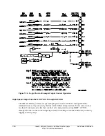
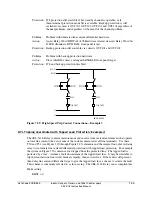
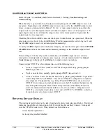
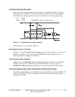
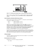
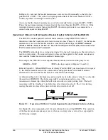
Refer to Figure 7.32 and the following discussion of an example setting group switching
discussion.
Setting Group 1 is the Active Setting Group
When setting Group 1 is the active setting group, optoisolated input IN102 operates as a reclose
enable/disable switch with the following settings:
SEL
OGIC
control equation settings:
79DTL = !IN102 + ...
[= NOT(IN102) + ...; drive-to-lockout setting]
DP1 = IN102
Text settings:
DP1_1 = 79 ENABLED
(displayed when DP1 = logical 1)
DP1_0 = 79 DISABLED
(displayed when DP1 = logical 0)
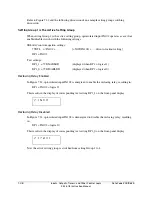
Reclosing Relay Enabled
In Figure 7.32, optoisolated input IN102 is energized to enable the reclosing relay, resulting in:
DP1 = IN102 = logical 1
This results in the display of corresponding text setting DP1_1 on the front-panel display:
&/"#-&%
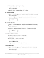
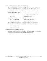
Reclosing Relay Disabled
In Figure 7.32, optoisolated input IN102 is deenergized to disable the reclosing relay, resulting
in:
DP1 = IN102 = logical 0
This results in the display of corresponding text setting DP1_0 on the front-panel display:
%*4"#-&%
Now the active setting group is switched from setting Group 1 to 4.
Summary of Contents for SEL-311L
Page 6: ......
Page 8: ......
Page 26: ......
Page 54: ......
Page 144: ......
Page 216: ......
Page 252: ......
Page 302: ......
Page 338: ......
Page 480: ......
Page 484: ......
Page 486: ......
Page 502: ......
Page 532: ...12 28 Standard Event Reports and SER Date Code 20010625 SEL 311L Instruction Manual 4 ...
Page 552: ......
Page 554: ......
Page 574: ......
Page 576: ......
Page 596: ......
Page 602: ......
Page 628: ......
Page 656: ......
Page 662: ......
Page 664: ......
Page 688: ......
Page 700: ......
Page 716: ......
Page 722: ......
Page 734: ......

