Date Code 20010625
Installation
2-7
SEL-311L Instruction Manual
M
AKING
R
EAR
-P
ANEL
C
ONNECTIONS
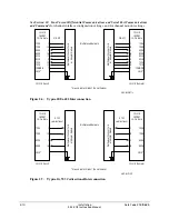
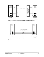
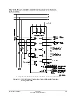
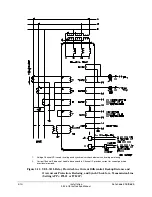
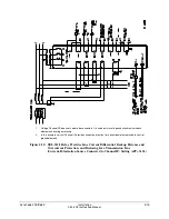
Refer to Figure 2.10, Figure 2.11, and Figure 2.12 for wiring examples of typical applications.
Tools:
Phillips or slotted-tip screwdriver
Parts:
All screw terminals are size #6-32. Locking screws can be requested from the factory.
Ground the relay chassis at terminal Z27.
Power Supply
Connect control voltage to the POWER terminals. Note the polarity indicators on terminals
Z25(+) and Z26(-). Control power passes through these terminals to a fuse and to the switching
power supply. The control power circuitry is isolated from the relay chassis ground.
Refer to
Section 1: Introduction and Specifications
for power supply ratings. The relay power
supply rating is listed on the serial number sticker on the relay rear panel.
Output Contacts
All SEL-311L Relays have six fast, high current interrupting output contacts (OUT201–
OUT206) and eight standard output contacts (OUT101–OUT107, ALARM). Refer to
General
Specifications
in
Section 1:
Introduction and Specifications
for output contact ratings. Refer
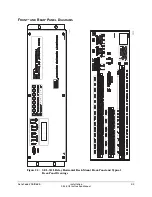
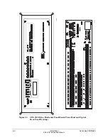
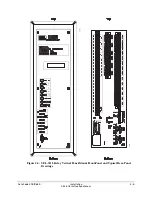
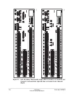
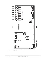
to Figure 2.2 through Figure 2.5 for output contact locations.
Use both types of contacts to switch either ac or dc loads.
Optoisolated Inputs
The optoisolated inputs in the SEL-311L Relay (IN101–IN106) are not polarity dependent and
are located on the main board. Refer to
General Specifications
in
Section 1: Introduction and
Specifications
for optoisolated input ratings.
Refer to the serial number sticker on the relay rear panel for the optoisolated input voltage rating.
Current Transformer Inputs
Note the polarity dots above terminals Z01, Z03, Z05, and Z07. Refer to Figure 2.10,
Figure 2.11, and Figure 2.12 for typical CT wiring examples.
Refer to the serial number sticker on the relay rear panel for the nominal current ratings (5 A or
1 A) for the phase (IA, IB, IC) and polarizing (IP) current inputs.
Potential Transformer Inputs (Optional Connections)
Note the signal labels (VA, VB, VC, N, VS, NS) on terminals Z09 through Z14. Figure 1.4
shows the internal connection for terminals VA, VB, VC, and VN. Note also that VS/NS is a
separate single-phase voltage input.
Summary of Contents for SEL-311L
Page 6: ......
Page 8: ......
Page 26: ......
Page 54: ......
Page 144: ......
Page 216: ......
Page 252: ......
Page 302: ......
Page 338: ......
Page 480: ......
Page 484: ......
Page 486: ......
Page 502: ......
Page 532: ...12 28 Standard Event Reports and SER Date Code 20010625 SEL 311L Instruction Manual 4 ...
Page 552: ......
Page 554: ......
Page 574: ......
Page 576: ......
Page 596: ......
Page 602: ......
Page 628: ......
Page 656: ......
Page 662: ......
Page 664: ......
Page 688: ......
Page 700: ......
Page 716: ......
Page 722: ......
Page 734: ......

