Date Code 20010625
Setting the Relay
9-45
SEL----311L Instruction Manual
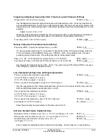
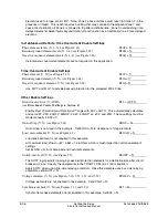
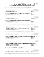
Tapped-Load Residual Ground Inst./Def.-Time Overcurrent Element Settings
Pickup (OFF, 0.50–16.00 A secondary)
T50GP = 7.22
Set the tapped-load ground overcurrent element with differential current. Since the transformers
are connected delta-wye, and T51G is a differential element, T51G will only assert for faults on the
transmission line. Use a setting of 50% of minimum residual current for a fault at Station T for this
example.
3466.9 A • 0.50 / 240 = 7.22
While this setting technically violates the “trip saving” philosophy—since the relay can operate on
faults between the transformer and breaker—this setting is a reasonable compromise.
Time delay (OFF, 0.00–16000.00 cycles)
T50GD = OFF
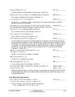
Backup Protection Transformer Ratio Settings
Polarizing (IPOL) Current Transformer Ratio (1–6000)
CTRP = 200
If a zero-sequence polarizing CT is available for directional control of the ground relays, enter the
CTR and include I in the ORDER setting (e.g., ORDER = QVI). This example does not have a
polarizing current transformer. The setting may remain at the default value.
Phase (VA, VB, VC) Potential Transformer Ratio (1.00–10000.00)
PTR = 2000
Synchronism Voltage (VS) Potential Transformer Ratio (1.00–10000.00)
PTRS = 2000
Set the potential transformer ratio PTR = 2000. The synchronizing PTR setting PTRS is not used.
The setting may remain at the default value.
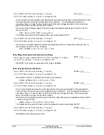
Line Parameter Settings (See
Settings Explanations
)
Positive-sequence line impedance magnitude
(0.05–255.00
Ω
secondary {5 A nom.};
0.25–1275.00
Ω
secondary {1 A nom.})
Z1MAG = 1.42
Positive-sequence line impedance angle (5.00–90.00 degrees)
Z1ANG = 84.7
Set line impedances to the shortest protected line section S to R to assure that the relay sets the
Z2R and Z0R thresholds correctly when E32 = AUTO.
Zero-sequence line impedance magnitude
(0.05–255.00
Ω
secondary {5 A nom.};
(0.25–1275.00
Ω
secondary {1 A nom.})
Z0MAG = 4.64
Zero-sequence line impedance angle (5.00–90.00 degrees)
Z0ANG = 73.00
Line length (0.10–999.00, unitless)
LL = 20.00
Enter the secondary line parameters for the line section S to R.
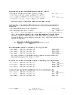
Distance Element Zones Enable Settings
Mho phase distance element zones (N, 1–4, 1C–4C) (see Figures 3.26–3.28)
E21P = 3
Mho ground distance element zones (N, 1–4) (see Figures 3.29–3.31)
E21MG = 3
Quadrilateral ground distance element zones (N, 1–4)
(see Figures 3.32–3.34)
E21XG = N
Zone 1 elements underreach with no intentional time delay. Zone 2 phase is an overreaching
Summary of Contents for SEL-311L
Page 6: ......
Page 8: ......
Page 26: ......
Page 54: ......
Page 144: ......
Page 216: ......
Page 252: ......
Page 302: ......
Page 338: ......
Page 480: ......
Page 484: ......
Page 486: ......
Page 502: ......
Page 532: ...12 28 Standard Event Reports and SER Date Code 20010625 SEL 311L Instruction Manual 4 ...
Page 552: ......
Page 554: ......
Page 574: ......
Page 576: ......
Page 596: ......
Page 602: ......
Page 628: ......
Page 656: ......
Page 662: ......
Page 664: ......
Page 688: ......
Page 700: ......
Page 716: ......
Page 722: ......
Page 734: ......

