Date Code 20010625
Setting the Relay
9-47
SEL----311L Instruction Manual
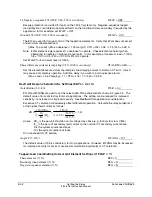
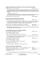
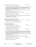
Frequency Elements (N, 1–6)
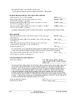
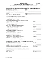
E81 = N
Frequency elements are not enabled in this example. Set E81 = N.
Fault location (Y, N) (see Table 12.1 and
Fault Location
in
Section 12
)
EFLOC = Y
Fault location is enabled in this example. Set EFLOC = Y.
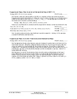
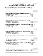
Loss-of-potential (Y, Y1, N) (see Figure 4.1)
ELOP = Y1
Set ELOP = Y1 to disable all voltage polarized directional overcurrent elements and distance
elements during a loss-of-potential.
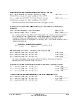
Communications-assisted trip scheme (N, DCB, POTT, DCUB1, DCUB2)
(see
Communications-Assisted Trip Logic—General Overview
in
Section 5
)
ECOMM = N
Reclosures (N, 1–4) (see
Reclosing Relay
in
Section 6
)
E79 = 1
Use single shot reclosing in this example. Set E79 = 1.
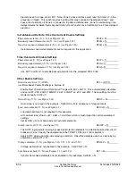
Zone 1 extension (Y, N) (see Figure 3.38)
EZ1EXT = N
Zone 1 extension is not used. Set EZ1EXT = N.
CCVT transient detection (Y, N) (see Figure 4.2)
ECCVT = Y
CCVT transients can cause Zone 1 distance elements to overreach. If CCVT transient blocking is
enabled and the relay detects a Source Impedance Ratio (SIR) greater than five during a fault, the
relay delays Zone 1 tripping for up to 1.5 cycles, allowing the CCVT to stabilize. Other settings are
not required. The relay automatically adapts to different system SIR conditions and determines
whether the 1.5 cycle delay is needed. In this example, the CCVTs use active ferroresonance
suppression. Set ECCVT = Y.
SEL
OGIC
®
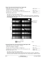
control equation Variable Timers (N, 1–16)
(see Figures 7.24 and 7.25)
ESV = N
Set ESV = N. No SEL
OGIC
variables are required.
SEL
OGIC
Latch Bits (N, 1–16)
ELAT = N
Set ELAT = N. No latches are required.
SEL
OGIC
Display Points (N, 1–16)
EDP = 2
Use two display points in this example. Set EDP = 2.
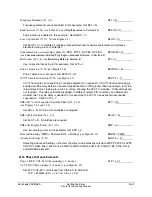
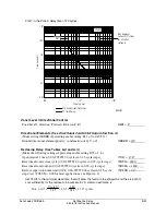
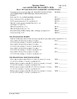
Demand Metering (THM = Thermal; ROL = Rolling) (see Figure 8.13)
EDEM = THM
Advanced settings (Y, N)
EADVS = N
Selecting Advanced Settings = N allows the relay to automatically calculate 50PP2, 50PP3, 50PP4,
XGPOL, TANG, 50L2, 50L3, 50L4, 50GZ2, 50GZ3, 50GZ4, k0M, k0A, X1B6, X1B5, R1L6, R1L5,
and UBOSBF elements.
Mho Phase Distance Elements
Zone 1 (OFF, 0.05–64.00
Ω
secondary {5 A nom.};
0.25–320.00
Ω
secondary {1 A nom.}) (see Figure 3.29)
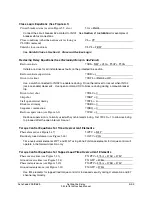
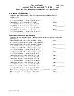
Z1P = 1.13
Set Z1P to 75–90% of distance from Station S to Station R.
Z1P = Z1MAG • 80% = 1.41
Ω
• 0.8 = 1.13
Ω
Summary of Contents for SEL-311L
Page 6: ......
Page 8: ......
Page 26: ......
Page 54: ......
Page 144: ......
Page 216: ......
Page 252: ......
Page 302: ......
Page 338: ......
Page 480: ......
Page 484: ......
Page 486: ......
Page 502: ......
Page 532: ...12 28 Standard Event Reports and SER Date Code 20010625 SEL 311L Instruction Manual 4 ...
Page 552: ......
Page 554: ......
Page 574: ......
Page 576: ......
Page 596: ......
Page 602: ......
Page 628: ......
Page 656: ......
Page 662: ......
Page 664: ......
Page 688: ......
Page 700: ......
Page 716: ......
Page 722: ......
Page 734: ......


