Date Code 20011112
Line Current Differential, Distance, Out-of-Step, Overcurrent,
3-7
Voltage, Synchronism Check, and Frequency Elements
SEL-311L Instruction Manual
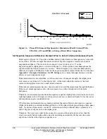
Another possible source of phase angle error might be line-charging current. However, since we
are discussing internal three-phase faults, line-charging current is not a source of significant error.
See
Appendix J: Example Calculations for 87L Settings
for a more thorough discussion of line
charging current.
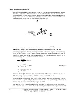
From this discussion, it is apparent that given severe combinations of asymmetrical channel
delay, system non-homogeneity and load angle, and CT saturation, an internal three-phase fault
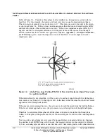
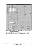
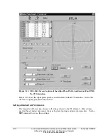
should lie within about 82 degrees of the positive real axis. System conditions that cause points
to lie outside that region can safely be considered non-internal faults (external faults, load current,
etc.). All of these conditions are extreme. We shall see that the SEL-311L Relay handles them
all easily without settings modifications, even if all conditions exist simultaneously.
Phase 87L Settings and Alpha Plane Settings
Three settings control operation of the phase 87L elements. Refer to Figure 3.3.
87LANG
The angular extent of the restraint region.
87LR
The outer radius of the restraint region (the inner radius is the reciprocal of
87LR).
87LPP
The difference current which qualifies tripping when the Alpha plane ratio lies
outside the restraint region.
Settings 87LANG and 87LR are common for all differential elements. There are not separate
restraint region settings for each type of element.
Three-phase fault protection places the highest constraints on setting 87LANG, because of source
angle considerations. Set 87LANG as describe above considering maximum load angle, system
non-homogeneity, asymmetrical channel delay and CT saturation. For this example, set 87LANG
to 360 - (82 • 2) = 196 degrees. The factory default setting is 195 degrees. Even if your
installation cannot experience these conditions, consider leaving 87LANG = 195 degrees.
Extensive testing at SEL demonstrates that this setting provides a good balance of security and
dependability.
87LR defines the outer radius of the restraint region, and the reciprocal of 87LR defines the inner
radius of the restraint region. Set 87LR to exclude from the restraint region all internal
three-phase faults, including those with zero-infeed. An 87LR setting of 6 gives an outside radius
of 6 and an inside radius of 1/6. This comfortably excludes zero-infeed conditions from the
restraint region.
Set 87LPP to reliably detect all internal three-phase faults. 87LPP must be set above line
charging current. Set 87LPP above maximum expected load current to prevent misoperation
when a ganged set of CT test switches is left shorted at one line end. The factory default setting
for 87LPP is 1.2 times nominal secondary current (6 A for a 5 A relay or 1.2 A for a 1 A relay)
and probably does not need to be changed except for special conditions.
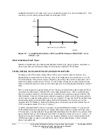
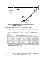
The settings defined above are factory default. They are also the setting used to produce the
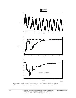
operate speed curves shown in Figure 3.6 (using high-speed output contacts).
Summary of Contents for SEL-311L
Page 6: ......
Page 8: ......
Page 26: ......
Page 54: ......
Page 144: ......
Page 216: ......
Page 252: ......
Page 302: ......
Page 338: ......
Page 480: ......
Page 484: ......
Page 486: ......
Page 502: ......
Page 532: ...12 28 Standard Event Reports and SER Date Code 20010625 SEL 311L Instruction Manual 4 ...
Page 552: ......
Page 554: ......
Page 574: ......
Page 576: ......
Page 596: ......
Page 602: ......
Page 628: ......
Page 656: ......
Page 662: ......
Page 664: ......
Page 688: ......
Page 700: ......
Page 716: ......
Page 722: ......
Page 734: ......


