H-12
Distributed Network Protocol (DNP) 3.00 Level 2
Date Code 20010625
SEL-311L Instruction Manual
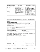
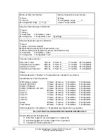
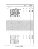
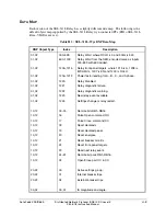
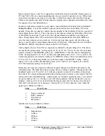
Binary inputs (objects 1 and 2) are supported as defined by the previous table. Binary inputs 0
–
599 and 1200
–
1223 are scanned approximately once per second to generate events. When time
is reported with these event objects, it is the time at which the scanner observed the bit change.
This may be significantly delayed from when the original source changed and should not be used
for sequence-of-events determination.
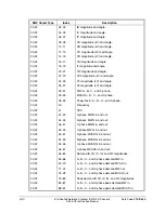
In order to determine an element’s point index, consult the Relay Word Bits table in
Section 9:
Setting the Relay.
Locate the element in question in the table and note the Relay Word row
number. From that row number, subtract the row number of the first Relay Word row (usually 2)
and multiply that result by 8. This is the index of the right-most element of the Relay Word row
of the element in question. Count over to the original element and add that to get the point
index. Binary Inputs 600
–
1199 are derived from the Sequential Events Recorder (SER) and
carry the time stamp of actual occurrence. Static reads from these inputs will show the same
data as a read from the corresponding index in the 0
–
599 group. Only points that are actually in
the SER list (SET R) will generate events in the 600
–
1199 group.
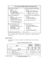
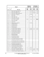
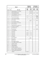
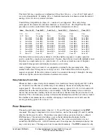
Analog Inputs (objects 30 and 32) are supported as defined by the preceding table. The values
are reported in primary units. Analog inputs 28
–
35, 42
–
57, 63
–
78, 84
–
102, and 104 are further
scaled according to the DECPLM setting (e.g., if DECPLM is 3, then the value is multiplied by
1000). Analog inputs 58
–
62, 79
–
83, and the even-numbered points in 0
–
7, 16
–
21, and 112
–
146
(current magnitudes) are scaled according to the DECPLA setting. The even-numbered points in
8
–
15 and 22
–
27 (voltage magnitudes) are scaled according to the DECPLV setting. Analog
inputs 36
–
41, 106, and the odd-numbered points in 0
–
27 and 113
–
147 (angles) are scaled by
100. The remaining analogs are not scaled.
Event-class messages are generated whenever an input changes beyond the value given by the
ANADB setting. The dead-band check is done after any scaling is applied. The angles (the odd
numbered points in 0
–
27 and 113
–
147) will only generate an event if, in addition to their dead-
band check, the corresponding magnitude (the preceding point) contains a value greater than the
value given by the ANADB setting. Analog inputs are scanned at approximately a 1-second rate,
except for analogs 103
–
111. During a scan, all events generated will use the time the scan was
initiated. Analogs 103
–
111 are derived from the history queue data for the most recently read
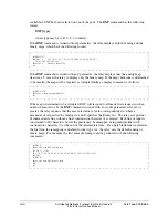
fault and do not generate event messages. Analog 103 is a 16-bit composite value, where the
upper byte is defined as follows:
Value Event
Cause
1
Trigger command
2
Pulse command
4
Trip element
8
ER element
And the lower byte is defined as follows:
Value Fault
Type
0
Indeterminate
1
A-Phase
2
B-Phase
4
C-Phase
8
Ground
Summary of Contents for SEL-311L
Page 6: ......
Page 8: ......
Page 26: ......
Page 54: ......
Page 144: ......
Page 216: ......
Page 252: ......
Page 302: ......
Page 338: ......
Page 480: ......
Page 484: ......
Page 486: ......
Page 502: ......
Page 532: ...12 28 Standard Event Reports and SER Date Code 20010625 SEL 311L Instruction Manual 4 ...
Page 552: ......
Page 554: ......
Page 574: ......
Page 576: ......
Page 596: ......
Page 602: ......
Page 628: ......
Page 656: ......
Page 662: ......
Page 664: ......
Page 688: ......
Page 700: ......
Page 716: ......
Page 722: ......
Page 734: ......

