Date Code 20010625
Distributed Network Protocol (DNP) 3.00 Level 2
H-13
SEL-311L Instruction Manual
The lower byte may contain any combination of the above bits (e.g., a 6 is a B to C fault and a 9
is an A to Ground fault). If Analog 103 is 0, fault information has not been read and the related
analogs (104
–
111) do not contain valid data.
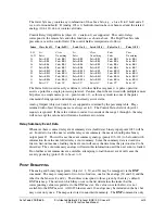
Control Relay Output Blocks (object 12, variation 1) are supported. The control relays
correspond to the remote bits and other functions, as shown above. The Trip/Close bits take
precedence over the control field. The control field is interpreted as follows:
Index Close (0x4X)
Trip (0x8X)
Latch On (3)
Latch Off (4)
Pulse On (1)
Pulse Off (2)
0-15
Set Clear
Set Clear Pulse Clear
16-23 Pulse
Do nothing
Pulse
Do nothing
Pulse
Do nothing
24
Pulse RB2
Pulse RB1
Pulse RB2
Pulse RB1
Pulse RB2
Pulse RB1
25
Pulse RB4
Pulse RB3
Pulse RB4
Pulse RB3
Pulse RB4
Pulse RB3
26
Pulse RB6
Pulse RB5
Pulse RB6
Pulse RB5
Pulse RB6
Pulse RB5
27
Pulse RB8
Pulse RB7
Pulse RB8
Pulse RB7
Pulse RB8
Pulse RB7
28
Pulse RB10
Pulse RB9
Pulse RB10
Pulse RB9
Pulse RB10
Pulse RB9
29
Pulse RB12
Pulse RB11
Pulse RB12
Pulse RB11
Pulse RB12
Pulse RB11
30
Pulse RB14
Pulse RB13
Pulse RB14
Pulse RB13
Pulse RB14
Pulse RB13
31
Pulse RB16
Pulse RB15
Pulse RB16
Pulse RB15
Pulse RB16
Pulse RB15
32
Pulse CC
Pulse OC
Pulse CC
Pulse OC
Pulse CC
Pulse OC
The Status field is used exactly as defined. All other fields are ignored. A pulse operation
asserts a point for a single processing interval. Caution should be exercised with multiple remote
bit pulses in a single message (i.e., point count > 1), as this may result in some of the pulse
commands being ignored and returning an already active status.
Analog Outputs (objects 40 and 41) are supported as defined by the preceding table. Flags
returned with object 40 responses are always set to 0. The Control Status field of object 41
requests is ignored. If the value written to index 0 is outside of the range 1 through 6, the relay
will not accept the value and will return a hardware error status.
Relay Summary Event Data
Whenever there is unread relay event summary data (fault data), binary input point 1023 will be
set. In order to load the next available relay event summary, the master should pulse binary
output point 15. This will cause the event summary analogs (points 103
–
111) to be loaded with
information from the next oldest relay event summary. Since the summary data is stored in a
first-in, first-out manner, loading the next event will cause the data from the previous load to be
discarded. The event summary analogs will retain this information until the next event is loaded.
If no further event summaries are available, attempting to load the next event will cause the
event type analog (point 103) to be set to 0.
P
OINT
R
EMAPPING
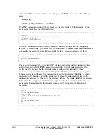
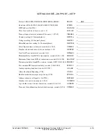
The analog and binary input points (objects 1, 2, 30, and 32) may be remapped via the
DNP
command. The map is composed of two lists of indices, one for the analogs (30 and 32) and the
other for the binaries (1 and 2). The indices correspond to those given by the relay’s default
DNP data map. The order in which they occur in the list determines the index that the
corresponding value is reported as to the DNP master. If a value is not in the list, it is not
available to the DNP master. All 1025 binaries and 112 analogs may be included in the list, but
may occur only once. The maps are stored in nonvolatile memory. The
DNP
command is only
Summary of Contents for SEL-311L
Page 6: ......
Page 8: ......
Page 26: ......
Page 54: ......
Page 144: ......
Page 216: ......
Page 252: ......
Page 302: ......
Page 338: ......
Page 480: ......
Page 484: ......
Page 486: ......
Page 502: ......
Page 532: ...12 28 Standard Event Reports and SER Date Code 20010625 SEL 311L Instruction Manual 4 ...
Page 552: ......
Page 554: ......
Page 574: ......
Page 576: ......
Page 596: ......
Page 602: ......
Page 628: ......
Page 656: ......
Page 662: ......
Page 664: ......
Page 688: ......
Page 700: ......
Page 716: ......
Page 722: ......
Page 734: ......

