J-4
Example Calculations for 87L Settings
Date Code 20010625
SEL-311L Instruction Manual
Source S
Z
1S
Source R
Relay 1
m • Z
1L
(1 - m) • Z
1L
Relay 2
Z
1R
I
1S
I
1R
+
Z
2S
Relay 1
m • Z
2L
(1 - m) • Z
2L
Relay 2
Z
2R
I
2S
I
2R
M311L144
—
I
1T
Z
0S
Relay 1
m • Z
0L
(1 - m) • Z
0L
Relay 2
Z
0R
I
0S
I
0R
0
I
1T
3 • R
F
I
TOTAL
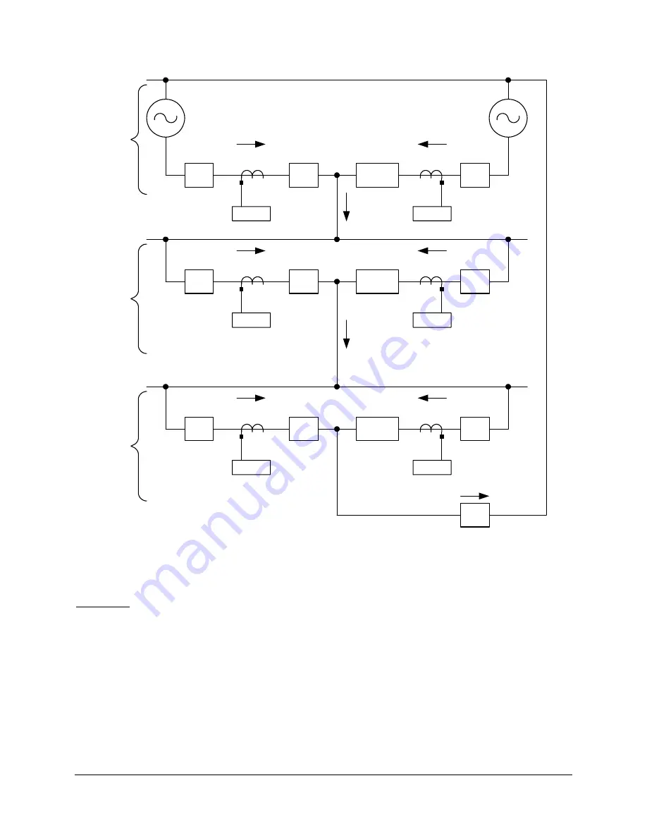
+ = Positive-Sequence Network
– = Negative-Sequence Network
0 = Zero-Sequence Network
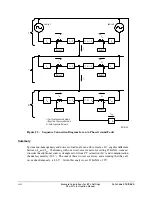
Figure J.3: Sequence Connection Diagram for an A-Phase Ground Fault
Summary
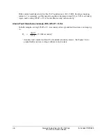
System non-homogeneity and non-zero load angle can add to create a 20° angular difference
between I
AR
and I
AL
. Continuing with our worst-case scenario for setting 87LANG, we must
consider the additional sources of angle errors from CT saturation (40°) and communication
channel asymmetry (22.5°). The sum of these worst-case errors, and assuming that they all
occur simultaneously, is 82.5°. Given this analysis, set 87LANG = 195°.
Summary of Contents for SEL-311L
Page 6: ......
Page 8: ......
Page 26: ......
Page 54: ......
Page 144: ......
Page 216: ......
Page 252: ......
Page 302: ......
Page 338: ......
Page 480: ......
Page 484: ......
Page 486: ......
Page 502: ......
Page 532: ...12 28 Standard Event Reports and SER Date Code 20010625 SEL 311L Instruction Manual 4 ...
Page 552: ......
Page 554: ......
Page 574: ......
Page 576: ......
Page 596: ......
Page 602: ......
Page 628: ......
Page 656: ......
Page 662: ......
Page 664: ......
Page 688: ......
Page 700: ......
Page 716: ......
Page 722: ......
Page 734: ......

