Date Code 20011112
Line Current Differential, Distance, Out-of-Step, Overcurrent,
3-35
Voltage, Synchronism Check, and Frequency Elements
SEL-311L Instruction Manual
V
B
V
AB
- rZ
• I
AB
Unfaulted
V
A
V
C
Test Angle
sin (
θ
< 180
°
) > 0
V
C
mem
-j •
V
AB
- 0
.25
• V
C
m
em
V
AB
- rZ
• I
AB
-j •
V
AB
- 0
.25
• V
C
m
em
Test Angle
sin (
θ
< 180
°
) > 0
V
A
V
B
V
C
V
AB
- rZ
• I
AB
-j •
V
AB
- 0
.25
• V
C
m
em
Test Angle
sin (
θ
> 180
°
) < 0
V
A
V
B
V
C
V
C
mem
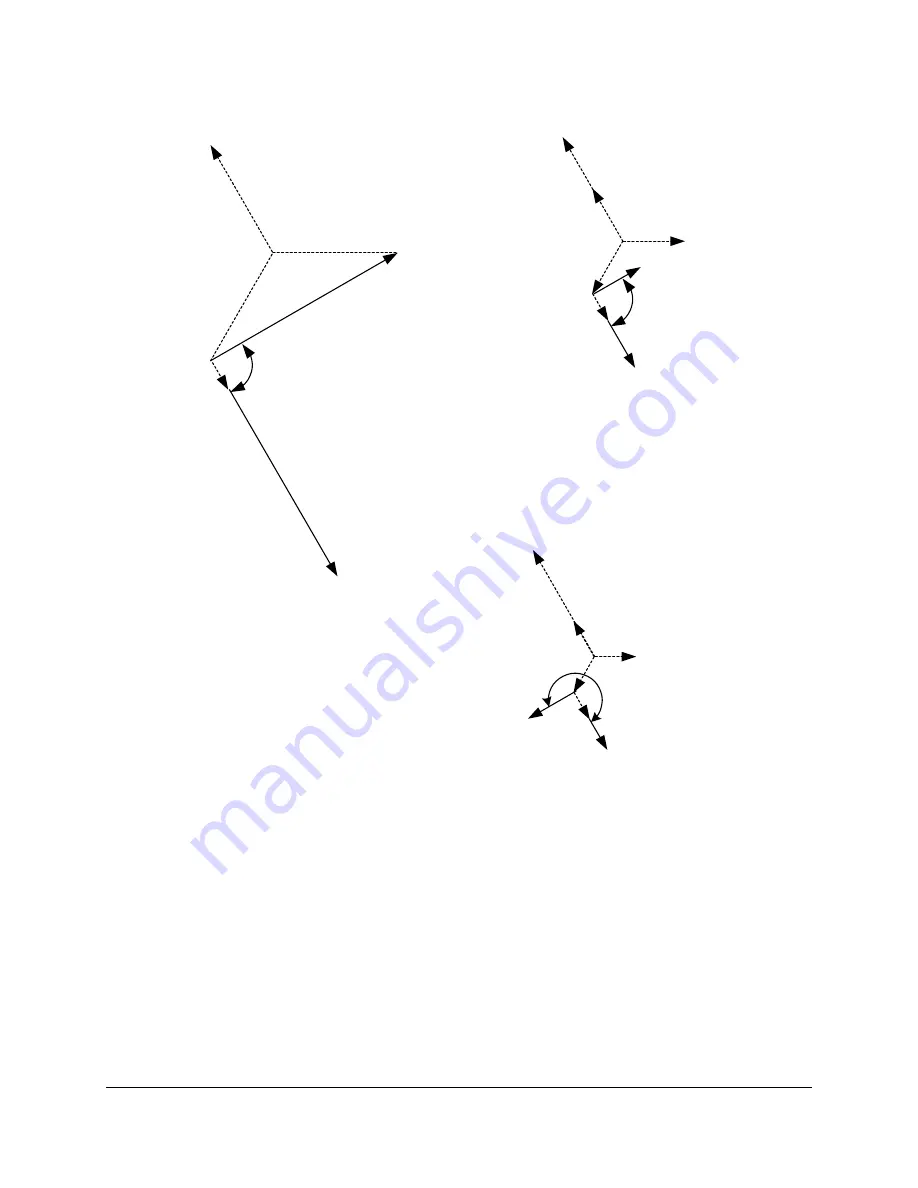
External Fault
Internal Fault
Note: V
A
, V
B
, and V
C
are internal element voltages, not system voltages.
V
C
mem
M311L115
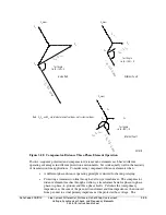
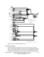
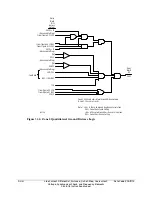
Figure 3.28: Compensator-Distance Three-Phase Element Operation
Positive-sequence polarized and compensator distance mho elements each have different
operating advantages in different protection environments, but work equally well in the majority
of transmission line applications. Consider using compensator distance elements when:
•
A different phase-distance operating principle is desired for backup relaying.
•
Protecting a transmission line through a delta-wye transformer. The compensator
distance element reaches through a delta-wye transformer bank for phase-to-phase,
phase-to-phase-to-ground, and three-phase faults. Calculate the total primary
impedance as the sum of the per-unit transformer and line impedances, then convert
from per-unit to actual primary impedance at the protected bus voltage. The
Summary of Contents for SEL-311L
Page 6: ......
Page 8: ......
Page 26: ......
Page 54: ......
Page 144: ......
Page 216: ......
Page 252: ......
Page 302: ......
Page 338: ......
Page 480: ......
Page 484: ......
Page 486: ......
Page 502: ......
Page 532: ...12 28 Standard Event Reports and SER Date Code 20010625 SEL 311L Instruction Manual 4 ...
Page 552: ......
Page 554: ......
Page 574: ......
Page 576: ......
Page 596: ......
Page 602: ......
Page 628: ......
Page 656: ......
Page 662: ......
Page 664: ......
Page 688: ......
Page 700: ......
Page 716: ......
Page 722: ......
Page 734: ......

