8-16
Breaker Monitor and Metering Functions
Date Code 20010625
SEL-311L Instruction Manual
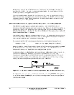
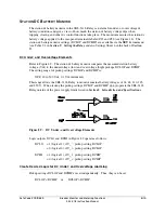
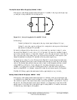
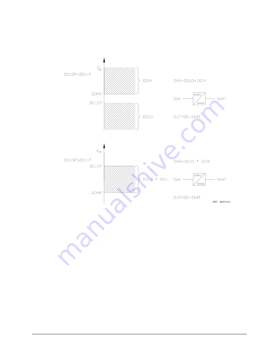
Figure 8.10 shows the resultant dc voltage elements that can be created with SEL
OGIC
control
equations for these two setting cases. In these two examples, the resultant dc voltage elements
are time-qualified by timer SV4T and then routed to output contact OUT106 for alarm purposes.
Figure 8.10: Create DC Voltage Elements With SEL
OGIC
Control Equations
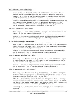
DCLO < DCHI (Top of Figure 8.10)
Output contact OUT106 asserts when:
V
dc
b
DCLOP
or
V
dc
r
DCHIP
Pickup settings DCLOP and DCHIP are set such that output contact OUT106 asserts when dc
battery voltage goes below or above allowable limits.
If the relay loses power entirely (V
dc
= 0 Vdc)
V
dc
= < DCLOP
then output contact OUT106 should logically assert (according to top of Figure 8.10), but cannot
because of the total loss of power (all output contacts deassert on total loss of power). Thus, the
resultant dc voltage element at the bottom of Figure 8.10 would probably be a better choice—see
following discussion.
Summary of Contents for SEL-311L
Page 6: ......
Page 8: ......
Page 26: ......
Page 54: ......
Page 144: ......
Page 216: ......
Page 252: ......
Page 302: ......
Page 338: ......
Page 480: ......
Page 484: ......
Page 486: ......
Page 502: ......
Page 532: ...12 28 Standard Event Reports and SER Date Code 20010625 SEL 311L Instruction Manual 4 ...
Page 552: ......
Page 554: ......
Page 574: ......
Page 576: ......
Page 596: ......
Page 602: ......
Page 628: ......
Page 656: ......
Page 662: ......
Page 664: ......
Page 688: ......
Page 700: ......
Page 716: ......
Page 722: ......
Page 734: ......

