Date Code 20010625
Installation
2-9
SEL-311L Instruction Manual
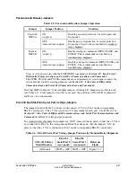
Table 2.1: EIA-232 Communications Cables to Connect the SEL-311L
Relay to Other Devices
SEL-311L EIA-232
Serial Ports
Connect to Device
(gender refers to the device)
SEL Cable No.
all EIA-232 ports
PC, 25
-
Pin Male (DTE)
C227A
all EIA-232 ports
Laptop PC, 9
-
Pin Male (DTE)
C234A
all EIA-232 ports
SEL
-
2020 or SEL-2030 without IRIG-B
C272A
2 SEL
-
2020 or SEL-2030 with IRIG-B
C273A
all EIA-232 ports
SEL
-
DTA2 C272A
2*
3*
StarComm Modem, 5 Vdc Powered
C220*
all EIA-232 ports
Standard Modem, 25
-
Pin Female (DCE)
C222
all EIA-232 ports
SEL-2100
C272A
2
SEL-2100 with IRIG
C273A
2
3
SEL-2505 SEL-2800
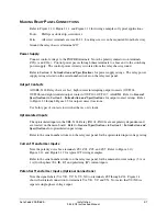
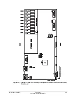
* A corresponding main board jumper must be installed to power the StarComm Modem with
+5 Vdc (0.5 A limit) from the SEL-311L Relay. See Figure 2.13 and Table 2.6.
IRIG----B Time-Code Input
The SEL
-
311L Relay accepts a demodulated IRIG
-
B time signal to synchronize the relay
internal clock with some external source. The line current differential protection does NOT rely
upon IRIG-B time synchronization.
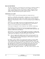
A demodulated IRIG-B time code can be input into Serial Port 2 on any of the SEL-311L Relay
models (see Table 10.2) by connecting Serial Port 2 of the SEL-311L Relay to an SEL-2020 with
Cable C273A, or by using an SEL-2810 Fiber-Optic Transceiver.
A demodulated IRIG-B time code can also be input into the connector for Serial Port 1 (see
Table 10.3). If demodulated IRIG-B time code is input into this connector, it should not be input
into Serial Port 2 and vice versa.
Line Current Differential Communications Channel Interfaces
Order the SEL-311L Relay with up to two line current differential interfaces. Each interface is
factory configured as EIA-422, CCITT G.703, IEEE Proposed Standard PC37.94 compliant
multimode fiber, or 1300 nm direct fiber. When the SEL-311L Relay arrives, the channels are
configured per your ordering options.
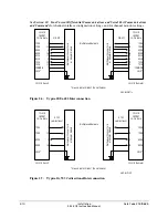
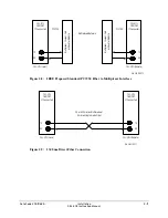
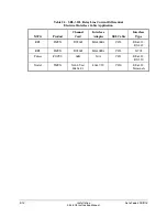
Table 2.2 shows the appropriate SEL cable to connect the SEL-311L Relay to some popular
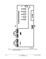
multiplexers for the electrical interfaces. Figure 2.6 and Figure 2.7 depict the signal names,
pinout and direction at the SEL-311L. All of the electrical 87L channel interface options on the
SEL-311L Relay are isolated from the chassis to at least 1500 V rms. To maintain that isolation,
and to avoid ground loops, ground all cable shields only at the communications equipment.
Summary of Contents for SEL-311L
Page 6: ......
Page 8: ......
Page 26: ......
Page 54: ......
Page 144: ......
Page 216: ......
Page 252: ......
Page 302: ......
Page 338: ......
Page 480: ......
Page 484: ......
Page 486: ......
Page 502: ......
Page 532: ...12 28 Standard Event Reports and SER Date Code 20010625 SEL 311L Instruction Manual 4 ...
Page 552: ......
Page 554: ......
Page 574: ......
Page 576: ......
Page 596: ......
Page 602: ......
Page 628: ......
Page 656: ......
Page 662: ......
Page 664: ......
Page 688: ......
Page 700: ......
Page 716: ......
Page 722: ......
Page 734: ......

