Date Code 20010625
Setting the Relay
9-41
SEL----311L Instruction Manual
Settings and Descriptions for this Example
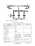
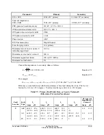
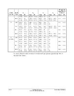
Following is a filled out example setting sheet for this application.
Identifier Labels and Configuration Settings (See Settings Explanations)
Relay Identifier (30 characters)
RID = SEL-311L 87L
Terminal Identifier (30 characters)
TID = EXAMPLE: BUS S, BREAKER 1
Local Phase (IA, IB, IC) Current Transformer Ratio
(1–6000)
CTR = 240
Application (87L, 87L21, 87L21P, 311L)
APP = 311L
APP = 311L displays all available settings in the relay. This example requires settings that are not
available in the special application settings.
Line Current Differential Configuration Settings
Relay operating mode (2, 3R, N)
E87L = 2
The relay has one differential channel. Set E87L = 2 for a two-terminal line.
High-speed tripping (1–6, N)
EHST = N
High-speed tripping is not needed with torque controlled tapped load overcurrent elements.
Enable high-speed direct transfer trip (Y, N)
EHSDTT = N
Enable disturbance detect (Y, N)
EDD = N
Set EHSDTT = N. The 87L elements are used only for tapped load element torque control.
High-speed direct transfer trip is not required. Disturbance detector supervision ensures the relay
detects a change in the local currents before allowing a trip due to 87L element assertion. Since
the 87L elements are used for torque control in this example, disturbance detect is not required.
Set EDD = N.
Tapped-load coordination (Y, N)
ETAP = Y
Set ETAP = Y for protection of a line with a tapped load.
CTR at terminal connected to Channel X (1–6000)
CTR_X = 240
Enter the current transformer ratio used in the SEL-311L Relay at Station R.
Minimum Difference Current Enable Level Settings (E87L = 2 or 3)
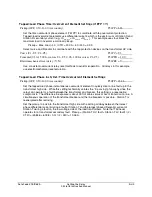
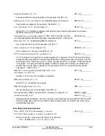
Phase 87L (OFF, 1.00–10.00 A secondary)
87LPP = 1.00
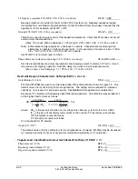
In an 87L protection application, set 87LPP above line charging current, and maximum load current.
This example uses the 87L elements as torque control for the tapped load elements. Torque
control element settings can be more sensitive than protection settings.
Set 87LPP = 1.0 A. With projected tap transformer load of 200 A primary or 0.83 A secondary, the
87L phase element does not assert under steady state load, but may operate momentarily on cold
load pickup.
Summary of Contents for SEL-311L
Page 6: ......
Page 8: ......
Page 26: ......
Page 54: ......
Page 144: ......
Page 216: ......
Page 252: ......
Page 302: ......
Page 338: ......
Page 480: ......
Page 484: ......
Page 486: ......
Page 502: ......
Page 532: ...12 28 Standard Event Reports and SER Date Code 20010625 SEL 311L Instruction Manual 4 ...
Page 552: ......
Page 554: ......
Page 574: ......
Page 576: ......
Page 596: ......
Page 602: ......
Page 628: ......
Page 656: ......
Page 662: ......
Page 664: ......
Page 688: ......
Page 700: ......
Page 716: ......
Page 722: ......
Page 734: ......


