3-18
Line Current Differential, Distance, Out-of-Step, Overcurrent,
Date Code 20011112
Voltage, Synchronism Check, and Frequency Elements
SEL-311L Instruction Manual
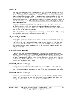
CTALRM (0.5–10 A Secondary)
Relay Word bit CTAA asserts when A-phase difference current exceeds setting CTALRM.
Similarly, CTAB and CTAC assert then B-phase or C-phase difference current exceeds setting
CTARLM. Use these bits to detect and alarm for excessive steady-state phase difference current,
such as might be caused when the CTs at one terminal are shorted. This setting is in secondary
Amps, referenced to the relay with the highest CTR setting.
87LR (2.0–8, Unitless)
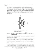
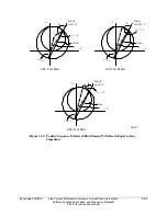
This setting controls the outside radius of the restraint region as shown in Figure 3.3. Unless
special circumstances warrant, set 87LR = 6 (the factory default).
87LANG (90–270 Degrees)
This setting controls the angular extend of the restraint region, as shown in Figure 3.3. Unless
special circumstances warrant, set 87LANG = 195 (the factory default).
OPO Open Pole Option (52, 27)
Do not use OPO = 27 in an application that requires 87L elements for tripping. OPO = 27 can
compromise logic that manages charging current inrush when a power line is energized.
Three-Terminal Protection With the SEL-311L
Three-Terminal Protection Logic
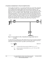
Use the 87L elements and other elements in the SEL-311L Relay for three-terminal line
protection. The SEL-311L Relay applies the Alpha plane concept introduced earlier to
three-terminal lines by combining (vectorly adding) currents from two of the terminals to produce
the remote current. The remaining (uncombined) current becomes the local current when
calculating the Alpha plane ratio of remote to local current. In other words, the SEL-311L Relay
converts the three-terminal line to an electrically equivalent two-terminal line, and then applies
two-terminal protection algorithms. All of the considerations described above in the two-terminal
discussion apply to three-terminal protection also.
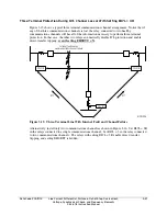
For internal faults with no outfeed and for external faults with no CT saturation, there is no wrong
way to choose which two currents to combine into the remote current, because all three
possibilities result in the correct trip/restrain decision.
The SEL-311L Relay processes all 87L elements using all three possible combinations of remote
current. Table 3.1 shows the three possibilities. The relay uses the trip/restrain decision from the
87L elements which use the maximum terminal current as the “local” current.
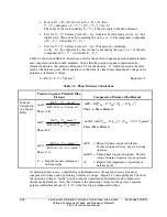
Table 3.1: Three Possible Combinations of Remote and Local Currents at Relay R.
Relays S and L Use the Same Three Combinations.
1 2 3
I
Remote
I
L
+ I
S
I
R
+ I
S
I
L
+ I
R
I
Local
I
R
I
L
I
S
Summary of Contents for SEL-311L
Page 6: ......
Page 8: ......
Page 26: ......
Page 54: ......
Page 144: ......
Page 216: ......
Page 252: ......
Page 302: ......
Page 338: ......
Page 480: ......
Page 484: ......
Page 486: ......
Page 502: ......
Page 532: ...12 28 Standard Event Reports and SER Date Code 20010625 SEL 311L Instruction Manual 4 ...
Page 552: ......
Page 554: ......
Page 574: ......
Page 576: ......
Page 596: ......
Page 602: ......
Page 628: ......
Page 656: ......
Page 662: ......
Page 664: ......
Page 688: ......
Page 700: ......
Page 716: ......
Page 722: ......
Page 734: ......

