9.36
SEL-351A Relay
Instruction Manual
Date Code 20080213
Setting the Relay
Settings Explanations
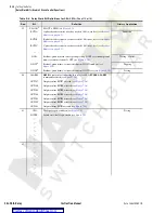
Example 2: Minimum CT Rating With an 80 A Instantaneous Setting
CT rating in terms of maximum fault current, X/R ratio, ANSI rating, and
burden is
Equation 9.4
With an 80 amp instantaneous setting, what is the minimum CT rating that can
be used when the maximum fault current is 40000 amps, X/R = 20, and the
burden is 0.50 W ohms
Equation 9.5
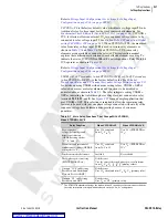
Example 3: Determine Whether the Following Application Meets the
Above Criteria
to verify if the CTs meet the required criteria.
Equation 9.6
The calculation shows that the 400:5 (class C400) CT meets the criteria in
Equation (1).
Settings for Voltage
Input Configuration
SEL-351A relays with firmware version R104 or lower can only accept wye-
connected PTs to the voltage inputs, and can only use voltage input
VS
as a
synchronism check voltage/auxiliary voltage input. Beginning with firmware
revision R105, these relays have two new global settings, PTCONN and
VSCONN; and a new group setting: VNOM.
NOTE:
VSCONN is not available in
the SEL-351A-1.
Voltage Input Configuration (See Settings for Voltage Input
Configuration on page 9.36) on page SET.20
.
PTCONN = WYE
is the factory default value. PTCONN = DELTA, if selected,
allows an open-delta PT connection. See
Delta-Connected Voltages (Global
setting PTCONN = DELTA) on page 2.14
for connection details. When
PTCONN = DELTA, the relay presents some different group settings, and
there is a change in some relay element availability, as compared to PTCONN
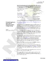
= WYE. Comparing
shows some of these changes.
This instruction manual explains these and other differences in relation to each
affected element or setting. To indicate the state of PTCONN in SEL
OGIC
control equations, Relay Word bit DELTA operates as shown in
CT
RATING
1
X
R
----
+
⎝
⎠
⎛
⎞
262.5
-------------------
100
ANSI
---------------
I
MAX
Z
B
• • •
=
CT
RATING
1
X
R
----
+
⎝
⎠
⎛
⎞
262.5
-------------------
100
ANSI
---------------
I
MAX
Z
B
• • •
=
1
20
+
(
)
262.5
--------------------
100
400
---------
40000
0.5
400 A
=
• •
•
=
CTs used
400:5 A, class C400
Instantaneous element pickup setting
80 A secondary
Maximum current for a line-to-line fault
40000 A primary
X/R ratio
20
Total CT secondary burden
0.50
Ω
ohm
X
R
----
1
+
⎝
⎠
⎛
⎞
I
f
Z
b
• •
20
1
+
(
)
40000
400
---------------
0.50
Ω
4
----------------
262.5
=
• •
=
Summary of Contents for SEL-351A
Page 10: ...This page intentionally left blank Courtesy of NationalSwitchgear com ...
Page 16: ...This page intentionally left blank Courtesy of NationalSwitchgear com ...
Page 34: ...This page intentionally left blank Courtesy of NationalSwitchgear com ...
Page 126: ...This page intentionally left blank Courtesy of NationalSwitchgear com ...
Page 184: ...This page intentionally left blank Courtesy of NationalSwitchgear com ...
Page 198: ...This page intentionally left blank Courtesy of NationalSwitchgear com ...
Page 228: ...This page intentionally left blank Courtesy of NationalSwitchgear com ...
Page 278: ...This page intentionally left blank Courtesy of NationalSwitchgear com ...
Page 384: ...This page intentionally left blank Courtesy of NationalSwitchgear com ...
Page 410: ...This page intentionally left blank Courtesy of NationalSwitchgear com ...
Page 450: ...This page intentionally left blank Courtesy of NationalSwitchgear com ...
Page 454: ...This page intentionally left blank Courtesy of NationalSwitchgear com ...
Page 472: ...This page intentionally left blank Courtesy of NationalSwitchgear com ...
Page 504: ...This page intentionally left blank Courtesy of NationalSwitchgear com ...
Page 558: ...This page intentionally left blank Courtesy of NationalSwitchgear com ...
Page 562: ...This page intentionally left blank Courtesy of NationalSwitchgear com ...
Page 586: ...This page intentionally left blank Courtesy of NationalSwitchgear com ...
Page 608: ...This page intentionally left blank Courtesy of NationalSwitchgear com ...
Page 666: ...This page intentionally left blank Courtesy of NationalSwitchgear com ...


