3.66
SEL-387-0, -5, -6 Relay
Instruction Manual
Date Code 20050919
Differential, Restricted Earth Fault, Thermal, and Overcurrent Elements
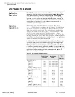
Overcurrent Element
Combined O/C Element Enable (EOCC)
Range: Y, N
Set EOCC = Y to enable combined overcurrent elements. A setting of
EOCC = N disables the elements.
Instantaneous and Definite-Time Element Pickups
(50PnmP, 50QnmP, 50NnmP)
Range: 1 A: OFF, (0.05–20), A secondary, in 0.01 A steps
5 A: OFF, (0.25–100), A secondary, in 0.01 A steps
Set pickups for the current level above which you want the elements to assert.
As the name of the instantaneous elements suggests, assertion occurs almost
immediately after current exceeds the threshold you specify. A definite-time
element asserts only after current exceeds the level you specify and after a
time delay that you specify with the definite-time delay setting.
Definite-Time Element Delays (50Pn1D, 50Qn1D, 50Nn1D)
Range: 0–16000 cycles, in 0.25-cycle steps
Select a time in cycles that you want definite-time elements to wait before
asserting.
Inverse-Time Element Pickups (51PnP, 51QnP, 51NnP, 51PCmP, 51NCmP)
Range: 1 A: OFF, (0.1–3.2), A secondary, in 0.01 A steps
5 A: OFF, (0.5–16), A secondary, in 0.01 A steps
The pickup setting acts as a horizontal scaling factor for an inverse-time
curve, because the curve formula uses current multiple of pickup as an input.
Set pickups, and the following three settings defining the time overcurrent
curve, to fit the practices of your organization, coordinate with upstream and
downstream devices such as fuses and motors, and accommodate transient and
fault conditions.
Curve Shape Settings (51PnC, 51QnC, 51NnC, 51PCmC, 51NCmC)
Range: U1, U2, U3, U4, U5
C1, C2, C3, C4, C5
This setting defines a particular curve equation for an inverse-time curve from
among five U.S. (U1–U5) and five IEC (C1–C5) curves.
Time-Dial Settings (51PnTD, 51QnTD, 51NnTD, 51PCmTD, 51NCmTD)
Range: US 0.5–15, IEC 0.05–1, in 0.01 steps
The time-dial setting acts to scale an inverse-time curve vertically, to vary the
output timing for a given multiple of pickup.
NOTE:
n = Winding 1, 2, 3, or 4;
m = Level 1, 2, 3, or 4.
NOTE:
For combined winding
element settings, m = 1: W1 + W2;
m = 2: W3 + W4.
NOTE
:
For combined winding
element settings, m = 1: W1 + W2;
m = 2: W3 + W4.
NOTE
:
For combined winding
element settings, m = 1: W1 + W2;
m = 2: W3 + W4.
Summary of Contents for SEL-387-0
Page 10: ...This page intentionally left blank ...
Page 16: ...This page intentionally left blank ...
Page 56: ...This page intentionally left blank ...
Page 350: ...This page intentionally left blank ...
Page 388: ...This page intentionally left blank ...
Page 456: ...This page intentionally left blank ...
Page 494: ...This page intentionally left blank ...
Page 528: ...This page intentionally left blank ...


