2.14
SEL-387-0, -5, -6 Relay
Instruction Manual
Date Code 20050919
Installation
Typical AC/DC Connections
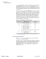
The dc connection diagram,
, illustrates tripping control of the three
power circuit breakers. The diagram includes three 52a input contacts to
define breaker status (open or closed) and a separate 86 lockout relay for
group tripping on a differential operation. Individual breaker trips occur for
overcurrent operation.
The diagram also shows
ALARM
and annunciation functions. The
ALARM
contact comes factory wired as a form-B contact, so that it closes under
conditions of complete relay power failure. If breaker closing control were
desired, we would use the Trip Annunciator contact (
OUT105
) as one of the
three separate output contacts for connection to the breaker closing coils. That
is, for this case the breaker trip and close functions together would require all
seven standard output contacts.
Figure 2.9
Example DC Connections (Basic Version)
SEL-387
(partial)
Power
Supply
A17
A18
IN101
IN102
IN103
TRIP
ANN
FAIL
ANN
OUT104 OUT105
ALARM
A19
A20
A21
A22
A07
A08
A09
A10
A15
A16
Z25
Z26
Z27
GND
A02
A04
A06
A01
A03
A05
+DC
–DC
+DC
–DC
+DC
–DC
+DC
–DC
Remaining: 3 Inputs (IN104–IN106)
2 Outputs (OUT 106, OUT107)
52-1
a
52-1
a
52-2
a
52-3
a
52-1
TC
52-2
TC
52-3
TC
52-2
a
52-3
a
86T
b
86T
a
86T
a
86T
a
86T
OP
Summary of Contents for SEL-387-0
Page 10: ...This page intentionally left blank ...
Page 16: ...This page intentionally left blank ...
Page 56: ...This page intentionally left blank ...
Page 350: ...This page intentionally left blank ...
Page 388: ...This page intentionally left blank ...
Page 456: ...This page intentionally left blank ...
Page 494: ...This page intentionally left blank ...
Page 528: ...This page intentionally left blank ...

